background image

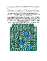
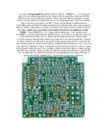
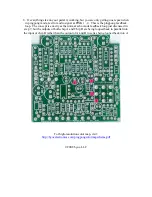
5. Test the dry audio signal path.  Do this using a Signal Test Probe.  If you look at the 

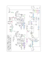
schematic, you'll see that “BLUE” locations 1 - 28 make up your direct dry audio signal 

path in order between the INPUT of the circuit and the OUTPUT of the circuit.  If you 

are getting no sound at all when the pedal is engaged, then this is the first place you need 

to look.  First know the what the terms “wet” and “dry” mean and the difference between 

the two.  Dry signal is your unaffected signal.  Do not confuse this with your bypass 

signal.  Dry signal is the guitar signal that passes through the input and output buffer 

circuits without changing the original tone at all(but the buffers may add or cut a very 

small amount of high frequency).  Wet signal, is where the dry signal gets split after the 

input buffer and is sent to actual delay circuit.   

Your wet and dry signals are mixed back together at R5/R6, so when your delay is 

working properly, you should here both wet and dry signals at BLUE18 - 28.  You will 

not hear any signal at any of the components that make contact with PIN6 of the ouput 

buffer op amp because of the nature of an inverting voltage gain configuration.  You can 

check your work at these points by testing for continuity between the unlabelled ends of 

R5, 6, 10, 11 and C6 to PIN6. 

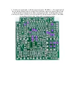
BLUE29 - 38 is where your dry signal is splits after the input buffer and travels to the 

input of the first delay chip at PIN16 of the “ping” PT2399. 


Содержание Digital Echo & Ping Pong Kit

Страница 1: ...hematic Understanding the circuit and Troubleshooting page 20 31 Please read through the instructions completely before beginning this project This is one of our most difficult kits and it is a little...

Страница 2: ...ed brown 2 15k brown green black red brown 2 511k green brown brown orange brown 1 2 2M red red black yellow brown Capacitors 1 47pf ceramic disc 1 470pf ceramic disc 471 4 0022uf film 222 or 2n2j 7 0...

Страница 3: ...continuing You might have to cut a slit in the cover with a blade and use a small screwdriver to get leverage 2 B100k linear 2 B50k linear Hardware 1 drilled enclosure w 4 screws 1 byoc pingpong kit c...

Страница 4: ...r follow the instructions in order Step 1 Add the three 1uf aluminum electrolytic capacitors to the underside of the PCB Aluminum electrolytic caps are polarized which means they have a positive side...

Страница 5: ...mper You can use some of the component clippings left over from the last step Step 3 Add the resistors Resistors are not polarized and can be inserted into the PCB in either direction The two 1k resis...

Страница 6: ...Step 4 Add the diode The end with the stripe cathode goes in the square solder pad The end with no stripe anode goes in the round solder pad...

Страница 7: ...e PCB or didn t clip off enough of the excess lead If your DIP16 socket does not seat perfectly clean up your soldering on the 1uf caps If it still does not seat perfectly it s OK Just as long as as t...

Страница 8: ...larized The positive side will have avery small symbol printed on the capacitor and should go in the square solder pad Step 8 Add the remaining seven 1uf aluminum electrolytic caps Remember that they...

Страница 9: ...ps small green caps highlighed in yellow and the one 47pf ceramic disc cap small round orange cap Step 10 Add remaining fourteen film caps yellow box caps highlighted in yellow and the one 470pf ceram...

Страница 10: ...Step 11 Add the larger aluminum electrolytic capacitors Remember that these are polarized and the positive end with the longer lead goes in the square solder pad...

Страница 11: ...Step 12 You should have two resistors left a 1k and a 10k These need to be mounted vertically They are not polarized so it does not matter which end goes where...

Страница 12: ...to tighten Orient the jacks so that if you are looking at the solder lug end of the jack the bevelled sleeve end would be pointing at 2 o clock and the sleeve of the out jack would be pointing at 7 o...

Страница 13: ...all the 3PDT toggle switch It does not matter which side you designate as the leading edge of the switch as long as you orient it so that the flat sides of the solder lugs are aligned in horizontal ro...

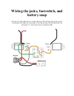
Страница 14: ...snap Because it s a little difficult to get to the solder lugs of the enclosed style jacks once the circuit board is mounted it s a good idea to wire this portion of the build and leave the ground an...

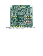
Страница 15: ...he actual soldering on the topsid of the PCB Read through all the steps in this portion before doing anything so that you can get the big picture Step 2 Install the LED but do not solder it or clip th...

Страница 16: ...e enclosure so that you can easily move them to line up with the eyelets on the PCB You may need to bend the leads of the pots into place if they were bent in shipping Step 4 once you have the PCB in...

Страница 17: ...Step 6 Solder the LED toggle switch and pots on the top side of the PCB Clip the excess LED leads Do not clip the leads of the pots...

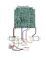
Страница 18: ...Wiring the PCB...

Страница 19: ...oth for orienting If the chip has both always refer to the u shaped notch first Install the base of the enclosure with the 4 screws that came with your kit Add the rubber bumper feet unless you re a v...

Страница 20: ...or the lowest voltage without going under 9V This will probably be 20V on most meters With the pedal footswitch in the engaged position you should get approximately 9VDC when you touch the red probe t...

Страница 21: ...let s check your offboard wiring first and make sure that you are getting signal to and from the PCB to rule that problem out Set your DMM to test for continuity Make sure your footswitch is in the EN...

Страница 22: ......

Страница 23: ...ocation you want to touch the probe to the exposed component or wire lead at that location and not to the PCB solder pad if possible If you are testing these various locations by touching the probe to...

Страница 24: ...RED location 1 but drop to 8 5V at location 2 and then drop again to 8 2V at location 3 This is to be expected But RED locations 3 8 should all remain constant and should be somewhere between 9V and...

Страница 25: ...reading should be approx half of what your Full Positive Voltage is after RED3 4 5V to 4V is to be expected Set your DMM to read 5VDC Touch the black probe to the sleeve of either jack Touch the red...

Страница 26: ...e Regulated 5V power supply This is the power supply provide by the 78L05 5 volt regulator Touch the black probe to ground Touch the red probe to the various GREEN locations They should all be approxi...

Страница 27: ...thout changing the original tone at all but the buffers may add or cut a very small amount of high frequency Wet signal is where the dry signal gets split after the input buffer and is sent to actual...

Страница 28: ...gnal from the output of the first delay chip to the input of the second when the pedal is in normal echo mode not pingpong mode If the first delay chip is receiving dry signal to PIN16 but is not prod...

Страница 29: ...ackloop The repeats knob is essentially a volume knob within the feedback loop It cuts the wet signal that goes back to the input of the delay circuit Each repeat that gets reduced in volume a little...

Страница 30: ...ck loop The concept is exactly as the normal echo mode feedback loop just discussed in step 7 but the outputs of both chip A and Chip B are being looped back in parallel into the input of chip B rathe...

Страница 31: ......

Отзывы: