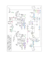
Checking your PCB
Ok....So Now you know bypass is working, signal is getting to and from the PCB, and
that the PCB also has a connection to +9V and ground. If you're still haveing trouble, it's
time to check your work on the PCB. Keep in mind that the PCB is simply a means of
connecting one component or wire to another component or wire. So when you touch
your probe to the test location, you want to touch the probe to the exposed component or
wire lead at that location and not to the PCB solder pad if possible. If you are testing
these various locations by touching the probe to a solder joint, then you must be certain
that the solder joint is sound.
USE A 9V POWER SUPPLY AND SET THE DELAY FOR NORMAL ECHO
MODE, NOT PINGPONG. ALL VOLTAGE READINGS WILL BE IN DC, NOT
AC.
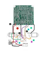
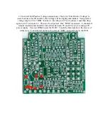
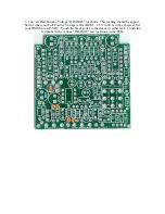
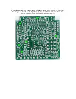
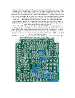
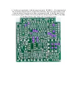
1. Check all ground connections. Set your DMM to test for continuity. Touch one probe
to the sleeve of either jack and touch the other probe to the various “BLACK” test
locations on the PCB.


