15” Panel PC User’s Manual
P21
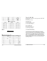
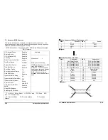
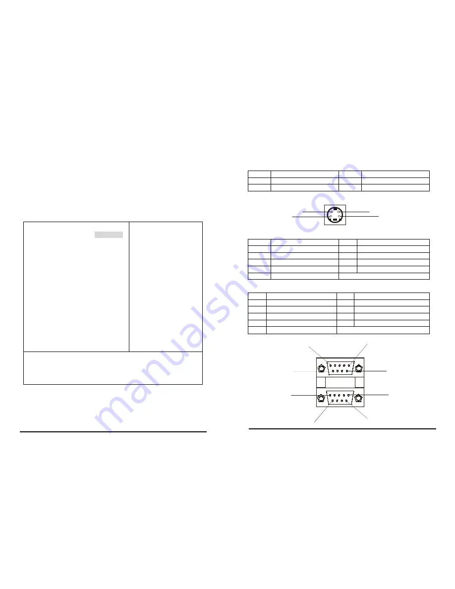
S-Video Connector (Mini Din 4 Pin):S-Video
7-4 IDE Adapters
Pin #
Assignment
Pin #
Assignment
1
Ground
2
Ground
3
LUM
4
CHROM
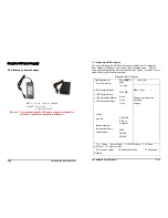
The IDE adapters control the hard disk drive. Use a separate sub menu to
configure each hard disk drive.
y
Figure:
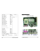
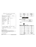
CMOS Setup Utility – Copyright © 1984 - 2001 Award Software
2
1
3
4
IDE Primary Master
IDE HDD Auto-Detection
IDE Primary Master
Access Mode
Cylinder
Head
Precomp
Landing Zone
Sector
Press Enter
Auto 2557
MB
Auto
4956
16
0
4955
63
Item Help
_______________________
Menu Level
¾¾
To auto-detect the HDD’s
size,
head... on this channel
↑↓←→
Move Enter: Select +/-/PU/PD: Value F10: Save
ESC: Exit F1: General Help
F5: Previous Values F6: Fail-safe defaults F7: Optimized
Defaults
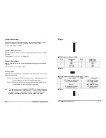
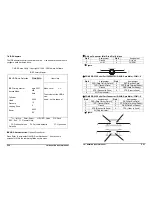
COM1 RS-232 Serial Port Connector (D-SUB 9-pin Male): COM1-2
Pin #
Assignment
Pin #
Assignment
1
DCD (Data Carrier Detect)
2
RXD (Receive Data)
3
TXD (Transmit Data)
4
DTR (Data Terminal Ready)
5
Ground
6
DSR (Data Set Ready)
7
RTS (Request to Send)
8
CTS (Clear to Send)
9
RI (Ring Indicator)
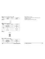
COM2 RS-232 Serial Port Connector (D-SUB 9-pin Male): COM1-2
Pin #
Assignment
Pin #
Assignment
1
DCD (Data Carrier Detect)
2
RXD (Receive Data)
3
TXD (Transmit Data)
4
DTR (Data Terminal Ready)
5
Ground
6
DSR (Data Set Ready)
7
RTS (Request to Send)
8
CTS (Clear to Send)
9
RI (Ring Indicator)
y
Figure:
5
1
6
5
9
1
6
9
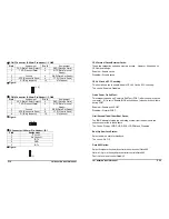
IDE HDD Auto-detection:
Options Press Enter
Press Enter to auto-detect the HDD on this channel. If detection is
successful, it fills the remaining fields on this menu.
P36
15” Panel PC User’s Manual

