


INSTRUCTION, USE AND
MAINTENANCE MANUAL
GB
Page 34 of 96
• Insert the bead wire on the rim with the stop ring
fitted (if the rim and bead wire feature fixing slits,
they must be in phase with each other).
• Move to work position
C
(
Fig. 6
).
• Place the tool holder arm on the external side then
lower it into “working” position (
Fig. 17 ref. 1
) with
the beading disc facing the wheel. If the outer edge
ring is not sufficiently fitted on the rim, position the
mandrel until the bead wire is near the beading disc.
Move the beading disc forward and then turn the
mandrel until the housing of the O-Ring (if featured)
is uncovered.
• Lubricated the O-Ring and place it in its housing.
• Move to work position
B
(
Fig. 6
).
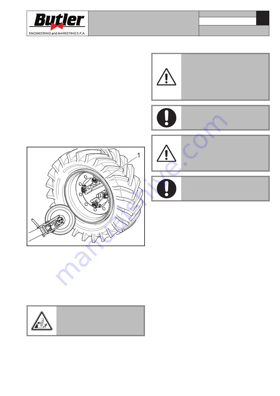
• Position the bead wire (
Fig. 47 ref. 1
) on the rim,
fit the stop ring with the help of the beading disc as
shown in
Fig. 47
.
Fig. 47
• Tilt up tool holder arm placing it in “out of work”
position (
Fig. 18 ref. 1
) after it has been unhooked.
• Position the movable footboard (
Fig. 1-2 ref. 18
)
directly under the wheel and lower the mandrel until
the wheel rests on the footboard.
• Close the mandrel jaws completely and translate the
footoboard outwards until the rim has been com-
pletely removed, making sure the wheel is held up
to avoid dropping.
CLOSING THE MANDREL CAUSES
THE WHEEL TO FALL. ALWAYS
MAKE SURE THAT NO ONE IS
STANDING BY ACCIDENT IN THE
WORK AREA.
13.0 ROUTINE MAINTENANCE
BEFORE CARRYING OUT ANY
ROUTINE MAINTENANCE OR AD-
JUSTMENT PROCEDURE, DISCON-
NECT THE MACHINE FROM THE
ELECTRICITY SUPPLY USING THE
SOCKET/PLUG COMBINATION AND
CHECK THAT ALL MOBILE PARTS
ARE AT A STANDSTILL.
BEFORE EXECUTING ANY MAIN-
TENANCE OPERATION, MAKE
SURE THERE ARE NO WHEELS
LOCKED ONTO THE MANDREL.
BEFORE REMOVING HYDRAULIC
CIRCUIT UNIONS OR PIPES, MAKE
SURE THAT THERE ARE NO PRES-
SURISED FLUIDS PRESENT. PRES-
SURISED OIL SPILLS MAY CAUSE
SERIOUS WOUNDS OR INJURIES.
BEFORE CARRYING OUT ANY
MAINTENANCE WORK ON THE HY-
DRAULIC CIRCUIT, SET THE MA-
CHINE IN THE REST CONDITION.
To guarantee the efficiency and correct functioning
of the machine, it is essential to carry out daily or
weekly cleaning and weekly routine maintenance, as
described below.
Cleaning and routine maintenance must be conducted
by authorized personnel and according to the instruc-
tions given below.
• Disconnect the mains power supply before starting
any cleaning or routine maintenance operations.
• Remove deposits of tyre powder and other waste
materials with a vacuum cleaner.
• DO NOT BLOW IT WITH COMPRESSED AIR.
• Periodically (preferably once a month) make a
complete check on the controls, ensuring that they
provide the specified actions.
• Every 100 working hours lubricate the tool carriage
sliding guides.
• Periodically (preferably once a month), grease all
moving parts of the machine (see
Fig. 48
).
7522-M004-1_B
NAV51.15 - NAV51T.15 - NAV51.15N


