INSTRUCTION, USE AND
MAINTENANCE MANUAL
GB
Page 22 of 66
F.
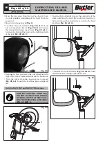
Turn the mandrel counterclockwise and, at the
same time, gradually move the tool carrier in-
wards to bead the tyre. Continue to turn the
mandrel while generously lubricating the tyre
rim and bead with a suitable lubricant. To avoid
risks, lubricate the beads by turning clockwise
if you are working on the outer side or counter-
clockwise if you are working on the inner side.
The more the wheel adheres to the rim, the slower
should the beading disc advance.
USE ONLY TYRE LUBRICANTS.
SUITABLE LUBRICANTS CONTAIN
NO WATER, HYDROCARBONS, OR
SILICON.
G.
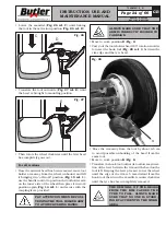
Once external beading has been carried out, unhook
and lift the tool holder arm placing it in “off-work”
position (
Fig.
_
15 ref.
_
1
); use the handle control to
position the tool holder arm on the inner side of
the wheel, then place it in work position (
Fig.
_
14
ref.
_
1
) and secure it with the special coupling lever.
PAY ATTENTION WHEN REPOSI-
TIONING THE TOOL HOLDER ARM
TO AVOID CRUSHING HANDS.
H.
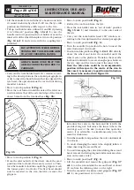
Carry out the tools holder head 180° rotation ac-
cording to the descriptions of the relevant para-
graph, so that the beading disc (
Fig.
_
19 ref.
_
1
) is
placed against the rim edge (
Fig.
_
19 ref.
_
2)
.
I.
Move to work position
D
(
Fig.
_
6
) and repeat the
operations described in points
E
,
F
until the tyre
has been completely beaded.
During all beading operations it is advisable to bend
the hook tool (
Fig
_
18
and
19 ref.
_
3
) to avoid obstacles
during the operating phases.
Fig.
_
19
2
1
3
7505-M001-3_B
NAV11N - NAV11NT
NAV11EI - NAV11TEI
12.6.2 Demounting
THROUGHOUT TYRE MOUNT-
ING/DEMOUNTING OPERATIONS,
CHECK THAT THE SELF-CEN-
TRING CHUCK CLAMPING PRES-
SURE IS CLOSE TO THE MAXIMUM
OPERATING VALUE (150 BAR).
Tubeless tyres can be removed in two ways:
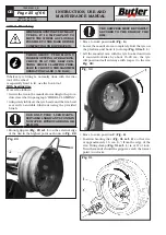
A.
If the wheel does not present particular problems,
continuing beading operation will completely dis-
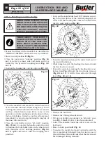
lodge the beads from the rim. The inner bead,
pushed by the disc, presses against the outer one
till it has been completely removed (see
Fig.
_
20
).
Fig.
_
20
B.
If the wheel is especially hard, it is not possible to
carry out the procedure described in point
A
. A
different procedure will be necessary: use the hook
tool and follow this sequence of operations:
• Move to work position
C
(
Fig.
_
6
).
Only for NAV11N and NAV11EI
versions
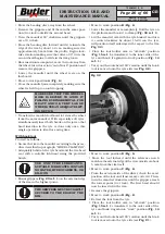
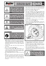
• Position the tool holder arm on the outer side of the
wheel and bring forward the hook tool, inserting it
between rim and bead until it is secured to the bead
itself (see
Fig.
_
21
).
Fig.
_
21

