


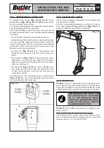


Page 18 of 41
GB
INSTRUCTION, USE AND
MAINTENANCE MANUAL
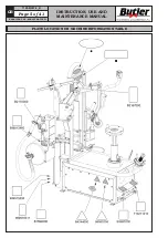
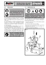
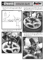
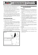
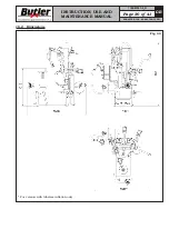
13.4 Wheel clamping
All wheels must be locked on the rubber plate (
Fig. 17
ref. 1
) through the central hole using the proper locking
device (
Fig. 17 ref. 2
).
Fig. 17
IN CASE OF USE OF RIMS WITH-
OUT CENTRAL HOLE, IT’S NECES-
SARY TO USE THE PROPER FIX-
TURE (AVAILABLE ON DEMAND).
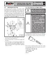
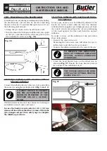
To lock a rim proceed as follows:
1. Dowel the wheel (
Fig. 18 ref. 1
) on the locking
platform and check that the dragging pin (
Fig. 18
ref. 2
) enter in a hole placed on the rim hub.
Fig. 18
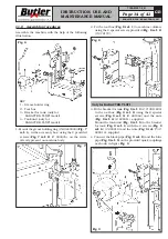
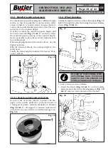
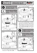
13.3 Mandrel height adjustment
The mandrel with central locking has 3 different height
modes, so that it is possible to operate with a wider
range of wheels. A “quick release” system allows to
remove the mandrel mobile part and to dowel the sup-
port plate at the required height.
In order to adjust the central support’s height, pull
the knob outwards (
Fig. 15 ref. 1
) and lift or lower
the central support’s plate up to the required height.
Now it’s possible to place the tyre in the right way with
the working tools.
When employing wheels with oversize off-set, use the
highest position.
With the standard wheels, the average height is nor-
mally used
Finally, the lowest height is indicated for reverse “drop-
center” wheels.
Fig. 15
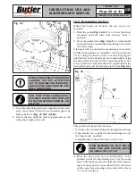
13.3.1 Reverse wheel pan protection
In case of use of reverse wheels, to protect the rim,
apply on the rubber platform a protection made of
a transparent plastic material available on demand
(
Fig. 16 ref. 1
). We suggest a constant replacement
of it and in any case if there are visible damages (see
Fig. 16
).
Fig. 16
1
KARACTER.TLX - KARACTER.TLXFI
7108-M007-0_B