E. A hot water boiler installed above radiation level
must be provided with a low water cutoff device as
part of the installation.
If a low water cut-off is required, it must be mount-
ed in the system piping above the boiler.
The minimum safe water level of a hot water boiler
is just above the highest water containing cavity of
the boiler; that is, a hot water boiler must be full of
water to operate safely.
F. There are many possible causes of oxygen contami-
nation such as:
(1) Addition of excessive make-up water as a
result of system leaks.
(2) Absorption through open tanks and fittings.
(3) Oxygen permeable materials in the distribution
system.
In order to insure long product life, oxygen sources
should be eliminated. This can be accomplished by
taking the following measures:
(1) Repairing system leaks to eliminate the need
for addition of make-up water.
(2) Eliminating open tanks from the system.
(3) Eliminating and/or repairing fittings which
allow oxygen absorption.
(4) Use of non-permeable materials in the distribu-
tion system.
(5) Isolating the boiler from the system water by
installing a heat exchanger.
N
O
I
T
U
A
C
ll
i
w
r
e
t
a
w
r
e
li
o
b
f
o
n
o
i
t
a
n
i
m
a
t
n
o
c
n
e
g
y
x
O
r
e
li
o
b
l
e
e
t
s
d
n
a
n
o
r
i
f
o
n
o
i
s
o
r
r
o
c
e
s
u
a
c
.
e
r
u
li
a
f
r
e
li
o
b
o
t
d
a
e
l
n
a
c
d
n
a
,
s
t
n
e
n
o
p
m
o
c
t
o
n
s
e
o
d
y
t
n
a
r
r
a
w
d
r
a
d
n
a
t
s
s
'
m
a
h
n
r
u
B
n
e
g
y
x
o
y
b
d
e
s
u
a
c
s
m
e
l
b
o
r
p
r
e
v
o
c
.
r
e
t
a
w
r
e
li
o
b
f
o
n
o
i
t
a
n
i
m
a
t
n
o
c
4.
INSTALL BOILER CONTROL.
A. Pull bulb and capillary tube out of hole in back of
control. Insert bulb in immersion well on top of
boiler and secure control with set screw in control.
B. Secure flexible conduit to Jacket Wrapper side with
conduit clamp and sheet metal screw. Conduit must
be on same side of boiler as Swing Door hinges.
5.
MOVE BOILER TO PERMANENT POSITION by
sliding or walking.
6.
INSPECT FRONT AND REAR DOOR INSULATION
PIECES AND COMBUSTION CHAMBER LINER
A. OPEN SWING DOOR on front of boiler. Use
flashlight to inspect insulation pieces secured to
front and rear doors. Inspect Ceramic Fiber Blanket
secured to bottom of combustion chamber with
water glass adhesive. Replace any damaged pieces.
7.
CONNECT SUPPLY AND RETURN PIPING TO
HEATING SYSTEM
A. Hot water pipes shall have clearances of at least ½”
from all combustible construction.
B. Use a system by-pass if the boiler is to be operated
in a system which has a large volume or excessive
radiation where low boiler water temperatures may
be encountered (i.e. converted gravity circulation
system, etc.).
Valves should be located in the by-pass and return
line as illustrated in Figures 4 and 5 in order to
regulate water flow for maintenance of higher
boiler water temperature.
Set the by-pass and return valves to a half throttle
position to start. Operate boiler until the system
water temperature reaches its normal operating
range.
Adjust the valves to maintain 180°F to 200°F boiler
water temperature and greater than 120°F return
temperature. Adjust both valves simultaneously.
Closing the boiler return valve while opening the
by-pass valve will raise the boiler return tempera-
ture. Opening the boiler return valve while closing
the by-pass valve will lower the boiler return
temperature.
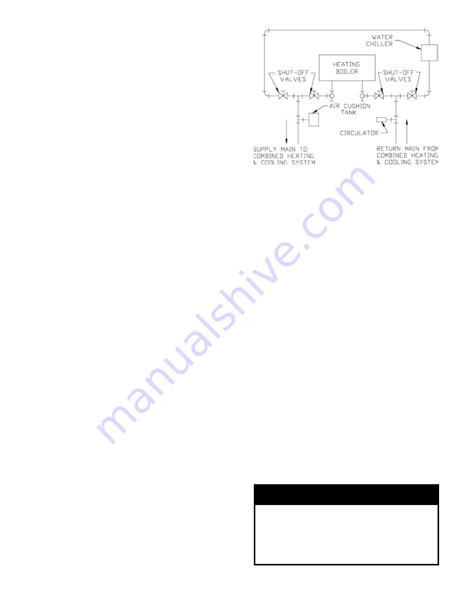
C. If this boiler is used in connection with refrigeration
systems, the boiler must be installed so that the
chilled medium is piped in parallel with the heating
boiler using appropriate valves to prevent the
chilled medium from entering the boiler, see Figure
6. Also consult I=B=R Installation and Piping
Guides.
D. If this boiler is connected to heating coils located in
air handling units where they may be exposed to
refrigerated air the boiler piping must be equipped
with flow control valves to prevent gravity circula-
tion of boiler water during the operation of the
cooling system.
Figure : Recommended Piping for
Combination Heating & Cooling
(Refrigeration) Systems
Содержание LE L7248
Страница 11: ...11 Figure 11C Wiring Diagram for LE Boilers with Riello Burner ...
Страница 22: ...22 Figure 19 LE Boiler Jacket Insulation ...
Страница 23: ...23 Figure 20 LE Bare Boiler Assembly ...
Страница 26: ...26 SERVICE RECORD DATE SERVICE PERFORMED ...


