background image

II.  Installation Instructions

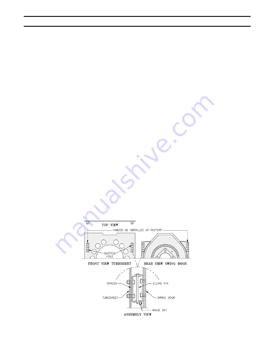
Figure 3:  Hinge Installation & Assembly, LE Boiler

1.

  REMOVE CRATE 

A.  Remove all fasteners at crate skid.
B.  Lift outside container and remove all other inside 

protective spacers and bracing. Remove container 

containing  Safety Relief Valve, Boiler Drain Valve 

and Pipe Fittings.

2.

  REMOVAL OF BOILER FROM SKID

A.  Tilt boiler, "walk" boiler backward, and set rear legs 

down on floor. Tilt boiler backward, pull skid 

forward and set front legs down on edge of skid. 

Install close coupling, tee, and plug in return 

coupling, see Step 7 and Figure 1. Point tee toward 

permanent return location.

B.  Tilt boiler backward and remove skid. Be careful not 

to damage Burner and Jacket.

3.


CHANGE HINGE POSITION if necessary.

A.  Look at the area where boiler will be installed.  If 

left side of boiler will be less than 12 inches from a 

wall, move hinges to right side of boiler.  See B 

through I below.

B.  Pull 2 halves of Burner Swing Door Interlock apart. 

Swing Door Interlock is connected to T-T terminals 

on R7184A Control. Lift Honeywell R7184A 

Control off of Burner Junction Box, open Burner 

Ignition Transformer and disconnect wiring harness 

from left side of burner.  Find round plastic cover 

inside Junction Box and install in hole in left side 

of burner.

C.  Remove 8 sheet metal screws from jacket.  Remove 

rear jacket box and bend both sides of Jacket 

Wrapper up, see Figure 19.

D.  Remove 2 (two) 5/16" - 18 x 3" long hex head cap 

screws and flatwashers from right side of door. 

Remove 2 hairpin cotter pins and 2 hinge pins from 

hinges on left side of door and remove Door 

Assembly from boiler.  Inspect Front and Rear 

Door Insulation Pieces and Combustion Chamber 

Liner, see Step 6.

E.  Remove 4 hex nuts from bolts that attach hinges and 

hinge spacers to left side of Tubesheet. Remove 4 

hex head cap screws that attach hinges to door.

F.  Attach 2 hinge brackets & spacers to Tubesheet and 

2 hinge brackets to Door on right side of boiler.  3 

Holes in each Hinge Bracket must line up with 3 

matching holes in Spacer, Tubesheet or Door. See 

Figure 3. Tighten hex nuts, bolts and screws by 

hand only.

G.  Replace door assembly.  Hinge brackets attached to 

door must rest on top of hinge brackets attached to 

tubesheet.  See Figure 3. Slide hinge pins through 

hinges from top and install cotter pins.  Close door 

and install 5/16" - 18 x 3" long hex head cap screws 

through flatwashers and left side of door and into 

tapped holes in tubesheet.  Tighten all hex nuts, 

bolts and screws.  When door is installed properly, 

it is parallel to Tubesheet when viewed from top 

and sides.

H.  Bend sides of Jacket Wrapper down and attach 2 

Jacket Straps to 4 slots at bottom of Jacket Wrapper 

sides with sheet metal screws.  Install Rear Jacket 

Box with 4 sheet metal screws. See Figure 19.

I.  Connect wiring harness to a knockout on right side 

of Junction Box and install Honeywell R7184A 

Control, see Wiring Diagram, Figures 11A and 11B. 

  Reconnect Swing Door Interlock.

Содержание LE L7248

Страница 1: ...T S N I E C I V R E S S E I R E S E L R E L I O B D E R I F L I O r e l i o b n o n o i t a m r o f n i g n i k e e s n e h W r o t c a r t n o c g n i t a e h r u o y l l a c r e l i o b o t s r i a p e r r o e c i v r e s r o F l e b a L g n i t a R n o n w o h s s a r e b m u N l a i r e S d n a r e b m u N l e d o M r e l i o B e d i v o r p r e b m u N l e d o M r e l i o B E L r e b m u N l ...

Страница 2: ...E OPERATING PROPERLY WHEN THE INSTALLATION IS COMPLETED 8 FOR OPTIMUM PERFORMANCE AND SERVICEABILITY FROM THIS UNIT ADHERE TO THE FOLLOWING RECOMMENDATIONS A DO NOT TAMPER WITH THE UNIT OR CONTROLS Retain your contractor or a competent serviceman to assure that the unit is properly adjusted and maintained B Clean Firetubes at least once a year preferably at the end of the heating season to remove ...

Страница 3: ...OILER in front of final position before removing crate See Figure 1 A LOCATE so that smoke pipe connection to chimney will be short and direct BOILER IS SUITABLE FOR INSTALLATION ON COMBUSTIBLE FLOOR Boiler can not be installed on carpeting B FOR BASEMENT INSTALLATION provide a solid base such as concrete if floor is not level or if water may be encountered on floor around Boiler C PROVIDE SERVICE...

Страница 4: ...cts Minimum free area of 1 square inch per 4 000 BTU per hour input of all equipment in space Duct cross sectional area shall be same as opening free area 3 Horizontal ducts Minimum free area of 1 square inch per 2 000 BTU per hour input of all equipment in space Duct cross sectional area shall be same as opening free area Alternate method for boiler located within confined space Use indoor air if...

Страница 5: ...r up see Figure 19 D Remove 2 two 5 16 18 x 3 long hex head cap screws and flatwashers from right side of door Remove 2 hairpin cotter pins and 2 hinge pins from hinges on left side of door and remove Door Assembly from boiler Inspect Front and Rear Door Insulation Pieces and Combustion Chamber Liner see Step 6 E Remove 4 hex nuts from bolts that attach hinges and hinge spacers to left side of Tub...

Страница 6: ... Figure 4 Recommended Water Piping for Zone Valve Zoned Heating Systems Figure 5 Recommended Water Piping for Circulator Zoned Heating Systems ...

Страница 7: ...ITION by sliding or walking 6 INSPECT FRONT AND REAR DOOR INSULATION PIECES AND COMBUSTION CHAMBER LINER A OPEN SWING DOOR on front of boiler Use flashlight to inspect insulation pieces secured to front and rear doors Inspect Ceramic Fiber Blanket secured to bottom of combustion chamber with water glass adhesive Replace any damaged pieces 7 CONNECT SUPPLY AND RETURN PIPING TO HEATING SYSTEM A Hot ...

Страница 8: ...reeching are not recommended 9 INSTALL ELECTRIC WIRING A Follow the National Electrical Code and local regulations A separate electrical circuit must be run from the main electrical service with an over current device disconnect in the circuit A service switch is recommended and may be required by some local jurisdictions Wiring should conform to Figures 11A 11B and 11C B CANADA Refer to CSA stand...

Страница 9: ... 10 Figure 9 T N A T R O P M I y l e t u l o s b a e b t s u m s n o i t a l l a t s n i e p i p e l g n i S t l u s e r y a m e m i r p f o s s o l r o s k a e l r o t h g i t r i a y l e t e l p m o c t i n u l e u f d n a e n i l d e e l B TWO PIPE OIL LINES For two pipe systems where more lift is required the two stage fuel unit is recommended Tables 2 single stage and 3 two stage show allowab...

Страница 10: ... a 10 second pre purge cycle If burner ignites within approximately 45 seconds and the cad cell sees flame the burner will continue to operate until the call for heat is satisfied or the setting of the high limit is reached The circulator will operate as long as the thermostat is calling for heat If the thermostat is not satisfied and the high limit is reached the circulator will continue to opera...

Страница 11: ...11 Figure 11C Wiring Diagram for LE Boilers with Riello Burner ...

Страница 12: ...rmanently lubricated bearings and thus do not require any field lubrication Water lubricated circulators do not need field lubrication Do not over lubricate This can cause as much trouble as no lubrication at all 5 ADJUST CONTROLS SETTINGS with burner service switch turned ON A SET ROOM THERMOSTAT about 10 above room temperature B PRESS RED RESET BUTTON C On WATER BOILERS WITHOUT TANKLESS HEATERS ...

Страница 13: ...place control Err4 B1 fault check B1 wiring voltage Err5 Low Line check L1 L2 110 Vac Err6 Fuse check ECOM wires replace fuse Err7 EEPROM HL Hdf reset to default values Restore desired settings Err8 Repeated B1 fault voltage present at B1 when output is turned off check B1 wiring voltage table 4 LED error codes 3 Error The controller has detected an error condition e g open sensor and has shut dow...

Страница 14: ... burners Items to be checked are nozzle size type and angle head size and setting on MD V1 head gun setting and positioning of electrodes This information is shown in Figure 15 and Table 6 If the desired boiler firing rate is 0 6 GPH the nozzle must be changed out the low firing rate baffle must be installed and the factory settings must be changed according to Table 6 These parts are in the bag a...

Страница 15: ...o exceed 1 with a minimum of excess air Make final check using suitable instrumentation to obtain a CO2 of 11 5 to 12 5 These settings will assure a safe and efficient operating condition If the flame appears stringy instead of a solid fire try another nozzle of the same type Flame should be solid and compact After all adjustments are made recheck for a draft of zero to 03 water gauge in breeching...

Страница 16: ...ndictor light turns on and control remains in Idle Mode 2 Simulate Flame Failure i Follow procedure to turn on burner ii Close hand valve in oil supply line iii Device enters recycle mode iv Device tries to restart system after approximately 60 seconds v Safety switch locks out approximately in safety switch timing indicated on label Indicator light flashes at 1 Hz rate Ignition and motor stop and...

Страница 17: ...are dissolved minerals and oxygen When the fresh cool make up water is heated in the boiler the minerals fall out as sediment and the oxygen escapes as a gas Both can result in reduced boiler life The accumulation of sediment can eventually isolate the water from contacting the steel When this happens the steel in that area gets extremely hot and eventually cracks The presence of free oxygen in th...

Страница 18: ... Long sleeved loose fitting clothing 3 Gloves 4 Eye Protection Take steps to assure adequate ventilation Wash all exposed body areas gently with soap and water after contact Wash work clothes separately from other laundry and rinse washing machine after use to avoid contaminating other clothes Discard used RCF components by sealing in an airtight plastic bag RCF and crystalline silica are not clas...

Страница 19: ... 8 4 Tank connection leaks There are various test kits available to trace air leaks such as electronic sight glasses Follow the manufacturers instructions to find air leaks The following actions can eliminate air leaks 1 Bleed pump as detailed previously 2 Replace flare fittings 3 Replace oil supply line 4 Repair oil filter leaks 5 Replace or repair tank fittings T N A T R O P M I d o o g y r e v ...

Страница 20: ...let brush hit rear door insulation piece or combustion chamber liner 3 AFTER CLEANING Vacuum debris inside bottom of rear door remove protective cloth and vacuum remaining fireside of boiler as necessary BE CAREFUL not to damage liner or rear door insulation piece Inspect front and rear door insulation pieces front door gaskets and combustion chamber liner for damage Replace any damaged pieces 4 C...

Страница 21: ... 717 481 8408 Figure 18 LE Boiler Trim Controls Item Description Qty Part Number 1 Honeywell L7248C1014 High Limit Circulator Relay OR Honeywell L4080B1261 High Limit 1 100059 01 80160402 2 Honeywell 123871A 3 4 NPT x 3 1 80160452 3 Conbraco 10 408 05 3 4 FPT 30 PSI Relief Valve 1 81660319 4 Temperature Pressure Gauge 1 1 2 DIA Long Shank 1 8056164U 5 Conbraco 35 302 03 3 4 FPT Drain Valve 1 80660...

Страница 22: ...22 Figure 19 LE Boiler Jacket Insulation ...

Страница 23: ...23 Figure 20 LE Bare Boiler Assembly ...

Страница 24: ...BECKETT AFG OIL BURNER REPAIR PARTS For replacement oil burner parts contact your wholesaler or the burner manufacturer R W Beckett Co P O Box 1289 Elyria OH 44036 440 327 1060 800 OIL BURN 645 2876 FAX 440 327 1064 ...

Страница 25: ... a l C e d o r t c e l E 9 1 2 4 y l b m e s s A r o t a l u s n I e d o r t c e l E 0 4 9 5 y l b m e s s A r e c a p S r e d i p S 5 5 6 5 3 7 8 5 e t a l P n o e h c t u c s E 3 9 4 3 1 4 9 5 t e k s a G 8 9 4 1 3 d a e H n o i t s u b m o C U 2 1 9 5 U 3 1 9 5 g u l P e l o H 9 3 1 2 l l e B t e l n I w y s s A g n i s u o H 7 7 8 5 r o t o M 6 5 4 2 r e t p a d A e l z z o N U 3 1 2 e d o r t...

Страница 26: ...26 SERVICE RECORD DATE SERVICE PERFORMED ...

Страница 27: ... the probe LWCO to the supply or return piping as shown below LWCO Location draining the heating system Many probe LWCO manufacturers recommend an annual inspection of the probe How to Wire LWCO s are available in either 120 VAC or 24 VAC configurations The 120 VAC configuration can be universally applied to both gas and oil boilers by wiring it in the line voltage service to the boiler after the ...

Страница 28: ...onditions set forth below U S Boiler Co Inc Lancaster Pennsylvania hereby extends the following limited warranties to the original owner of a residential grade water boiler manufactured and shipped on or after July 1 1991 ONE YEAR LIMITED WARRANTY ON RESIDENTIAL GRADE WATER BOILERS U S Boiler Co Inc warrants to the original owner that its residential grade water boilers comply at the time of manuf...

Отзывы: