Bunn CDBC Скачать руководство пользователя страница 8

Page 8

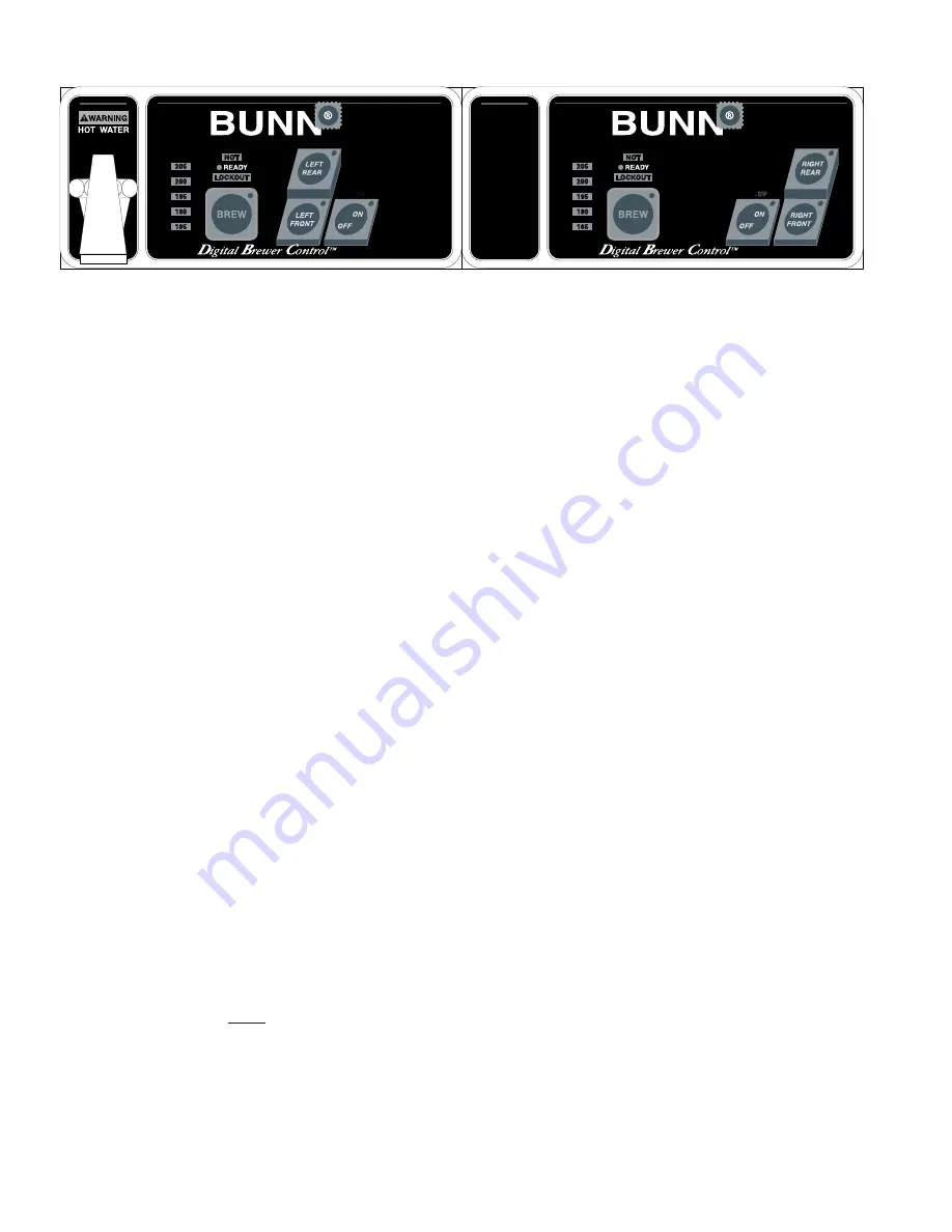
CDBC ADJUSTMENTS & OPTIONAL SETTINGS

HIDDEN

SWITCH

HIDDEN

SWITCH

NOTE:  

The following adjustments must be performed for each Brew Station.

Setting Brew Temperature

The brewer is factory set to brew at 200

°

F(95

°

C). To change this setting, press and hold the "HIDDEN" switch

beneath the "®". The word "TEMP" above the "ON/OFF" switch will glow to correspond with the temporary function
change of this switch. Repeatedly press and release the "ON/OFF" switch until one of the bank of temperature
indicators shows the approximate desired temperature. When two indicators are glowing, the temperature is
approximately the number between them.

Displaying Brew Temperature

The brewer is factory set with the temperature display disabled. To change this setting, press and hold the "ON/

OFF" switch and the "HIDDEN" switch beneath the "®" for five seconds, the entire bank of temperature indicators
will glow. Release both switches. Pressing and releasing the "ON/OFF" switch will toggle between turning the entire
bank of temperature indicators on-or-off, signifying the "ON" or "OFF" condition of this display. Wait for a few
seconds, the brewer will maintain this last setting.

Setting Brew Lockout

The brewer is factory set with the brew lockout disabled. Brew lockout prevents starting a brew cycle if the ready

indicator is not glowing. When an attempt at brewing cannot be allowed, the word "NOT" and "LOCKOUT" flash for
three seconds to indicate the reason the brew can't begin. To change the condition of the brew lockout, press and
hold the "HIDDEN" switch beneath the "®" and momentarily press the "BREW" switch.

Adjusting Automatic Warmer Shut-Off

The brewer is factory set with this feature disabled. The automatic warmer shut-off deenergizes all warmers

after a predetermined time period after the most recent brew cycle. To change the setting, press and hold the
"BREW" switch and the "HIDDEN" switch beneath the "®" for five seconds, the entire bank of temperature indicators
will flash on-and-off. Release both switches. Pressing and releasing the "BREW" switch will select the number of
temperature indicators from none to five. When no indicators are glowing, this feature is disabled and all warmers
will be controlled only by their respective switches. When one to five indicators are glowing, it indicates the
approximate number of hours of delay before all warmers will be automatically deenergized after the most recent
brew cycle.

IMPORTANT:

The tank 

must

 be full and refill solenoid shut off prior to making these adjustments.

Sprayhead must be installed while making these adjustments.

P1871

29319 030101

Содержание CDBC

Страница 1: ...FUN NE L CO NTE NTS AR E HO T CA UT IO N DIS CA RD DE CA NTE R IF CRA CKE D SCR ATC HED BOI LED DRY HEA TED WHE N EMP TY USE D ON HIG H FLA ME OR EXP OSE D ELE CTR IC ELE MEN TS FAI LUR E TO CO MP LY...

Страница 2: ...y claim to be made under this warranty by telephone at 217 529 6601 or by writing to Post Office Box 3227 Springfield Illinois 62708 3227 2 if requested by BUNN shipping the defective equipment prepai...

Страница 3: ...00656 0000 00658 0000 12364 0000 10044 0000 WARNING DO NOT OVERLOAD CIRCUIT ALWAYS ELECTRICALLY GROUND THE CHASSIS OR ADAPTOR PLUG DO NOT DEFORM PLUG OR CORD FOLLOW NATIONAL AND LOCAL ELECTRICAL CODE...

Страница 4: ...stall a regulator in the line when pressure is greater than 90 psi 620 kPa to reduce it to 50 psi 345 kPa The water inlet fitting is 3 8 flare Bunn O Matic does not recommend the use of a reverse osmo...

Страница 5: ...te and complete a brew cycle ADDITIONAL WARMER SWITCHES Placing any additional warmer switch in the ON upper position supplies power to the associated warmer READY INDICATOR This indicator glows when...

Страница 6: ...ethandle Releaseitwhenyouhearwateronceagainflowing into the tank 8 Model CDBC With the ON OFF switch still in the ON position indicator glowing momentarily press and release the BREW switch Model CEZ...

Страница 7: ...erisnowsettodispensethisamount of water for each subsequent brew cycle To increase the amount of water for each brew cycle place an empty funnel in the funnel rails and an empty decanter or graduated...

Страница 8: ...isfactorysetwiththebrewlockoutdisabled Brewlockoutpreventsstartingabrewcycleiftheready indicator is not glowing When an attempt at brewing cannot be allowed the word NOT and LOCKOUT flash for three se...

Страница 9: ...lease the BREW switch once for each ounce approximate of water to be added to the prior setting and allow the brew cycle to finish To decrease the amount of water for each brew cycle place an empty fu...

Страница 10: ...emory The spray will continue the off and on cyclesuntilthebrewvolumeofstep1iscomplete PressingtheOFF ONbuttonagainwillterminatethebrewing cycle with the parameters stored in memory 7 If only a preinf...

Страница 11: ...notices Before troubleshooting this brewer check for the following A Control Boards CDBC TWIN 1 Make sure ribbon cable is properly attached to the control board ALL PINS INSERTED INTO PLUG 2 Makesure...

Страница 12: ...check for lime deposit on tip Clean and rein stall Disconnect the brewer from the power source and remove wires from refill valve coil Check for con tinuity across the terminals of the solenoid coil I...

Страница 13: ...ctor from the control board Check for continuity from the nut on top of the level probe to pin 5 of the plug continuity should be present Pullthetemperatureprobe up about an inch from the grom met Che...

Страница 14: ...e up about an inch from the grommet Check for continuity from the outside surface of the temperature probe and pin 4 of the plug continuity should be present Connect the J3 plug to the control board a...

Страница 15: ...probe from the grommetandsubmergeinawater bathofapproximately70 F 21 C Connect an ohmmeter to pins 2 and 3 of the J5 connector At 60 F 16 C the reading should be 15 3k 2k OHMS at 70 F 21 C the readin...

Страница 16: ...board B Remove the probe from the grommetandsubmergeinawater bathofapproximately70 F 21 C Connect an ohmmeter to pins 2 and 3 of the J5 connector At 60 F 16 C the reading should be 15 3k 2k OHMS at 7...

Страница 17: ...ss the black and white terminals at the termi nal block The indicator lamp must be lit Allow brewer to heat until ready lamp is lit or disable the brew lockout feature See page 7 or 8 Press ON OFF swi...

Страница 18: ...inuity across the terminals of the sole noid coil If continuity is not present replace the solenoid See page 27 If continuity is present the valve may be stuck closed Set up brewer according to in str...

Страница 19: ...for proper ex traction Place an empty brew funnel on an empty decanter beneath the sprayhead Initiate brew cycle and check the water temperature im mediately below the sprayhead with a thermometer The...

Страница 20: ...t the brewer from the powersource Removethewarmer plate and turn upside down to ex pose the warmer terminals Re move the two wires Check for continuity across the two warmer terminals If continuity is...

Страница 21: ...pressure is water shut off Level probe dry for 7 minutes after fill valve is energized Shorting pin on J6 connector of control board not on correct set of pins CEZ boards only See page 7 Level probe w...

Страница 22: ...sistance in determining the cause of any problem WARNING Inspection testing and repair of electri cal equipment should be performed only by qualified service personnel The brewer should be unplugged w...

Страница 23: ...and Replacement 1 Disconnect the black wire and blue wire from the relay on the control board 2 Disconnect the 10 pin connector and the 4 pin connector from the main wiring harness 3 Disconnect the 1...

Страница 24: ...Remove the four 6 32 screws securing the con trol board to the component mounting bracket 5 Remove the four spacers from the control board and attach them to the new board 6 Locate J6 connector on con...

Страница 25: ...CH PANELS CDBC Removal and Replacement 1 Disconnect the 11 pin connector to the switch panel from the control board 2 Remove the four 6 screws nylon washers and the two 4 screws securing the control b...

Страница 26: ...described refer to the Wiring Diagrams and check the brewer wiring har ness 5 With the black wire removed remove the wire from the lower terminal 6 Check for continuity across the center and lower ter...

Страница 27: ...Check for continuity across the two terminals on the switch when it is held in the lower position Continuity must not be present across these ter minals when the switch is released P1851 P1849 FIG 7 B...

Страница 28: ...or wear and remove waterborne particles If the sound is not heard as described proceed to 6 P1877 P1853 WHI GRN from PC Control Board WHI from Terminal Block FIG 10 DISPENSE VALVE WIRING FIG 9 DISPENS...

Страница 29: ...el on the front side of the tanks Test Procedures 1 Disconnect the brewer from the power source 2 Disconnect the blue and black wires from the limit thermostat 3 Withanohmmeter checkforcontinuityacros...

Страница 30: ...hose from the top of the tank by pulling the elbow fitting from the grommet in the top of the tank lid 3 Drain water from the tank 4 Disconnect the water supply tube to the dispense valve from the si...

Страница 31: ...the grom met in the tank lid 24 Install the elbow fitting of the vent hose into the grommet in the tank lid 25 If installing left tank on brewers with faucet connect the outlet water line of the fauce...

Страница 32: ...continuity is not present as described replace the refill valve 6 Check the refill valve for coil action Connect the brewer to the power source With ON OFF switch in the ON upper position press start...

Страница 33: ...4 Disconnect the brewer from the power source If voltage is present as described proceed to 5 If voltage is not present as described refer to Wiring Diagrams and check brewer wiring harness 5 Check th...

Страница 34: ...YEL WHI YEL WHI ORA WHI ORA PNK WHI GRN COUNTER OPTIONAL PNK GRY t BLK BLK 14 WHI 120 208V AC 3 WIRE 120 240V AC 3 WIRE SINGLE PHASE P1 P2 P3 ARE PINS OF A POLARIZED THREE PIN CONNECTOR WHI SOL WHI W...

Страница 35: ...IRE SINGLE PHASE 120 208V AC 3 WIRE 120 240V AC 3 WIRE SINGLE PHASE YEL WHI VIO WHI VIO WHI VIO BLK WHI YEL YEL W H I LEFT CONTROL PANEL ASSY J2 1 J2 6 J2 11 BREW SW STATIC SHIELD ON OFF SW HIDDEN SW...

Страница 36: ...OPTIONAL 120 208V AC 3 WIRE 120 240V AC 3 WIRE SINGLE PHASE 120 208V AC 3 WIRE 120 240V AC 3 WIRE SINGLE PHASE VIO VIO BLK WHI LEFT CONTROL PANEL ASSY J2 1 J2 6 J2 11 BREW SW STATIC SHIELD ON OFF SW...

Отзывы: