Bunker Hill Security 91309 Скачать руководство пользователя страница 5

Page 5

SKU 91309

For technical questions, please call 1-800-444-3353.

Connecting the system (continued)

Operation (continued)

1. Set the Monitor (2) in a dry, stable position, out of the direct sunlight and in accordance with

the operational warnings above.  Set the Sunshade (8) on top of the Monitor (2).  Just a few
feet from the Camera (1), run the 65 Foot Cable (3) around a railing or post to keep the
weight of the Camera (1) from dislodging the Monitor (2) from its stable position.  Plug the
65 Foot Cable (3) into the Camera port (C1) on the back of the Monitor (2).  Refer to
FIGURE 2 on page 4,

2. Set the Battery (4) in a dry position, on a plate or other flat, stable surface out of the sun,

close enough for the Battery Cord (5) to reach the rear of the Monitor (2).  Attach the Black
(-) alligator clip on the Battery Cord (5) to the Black (-) terminal on the Battery (4).   Attach
the Red  (+) alligator clip on the Battery Cord (5) to the Red (+) terminal on the Battery (4).
Plug the other end of the Battery Cord (5) into the DC 12 Volt In input on the back of the
Monitor (2).

3. Set the VCR/Camera switch (on the back of the Monitor (2)) to Camera.
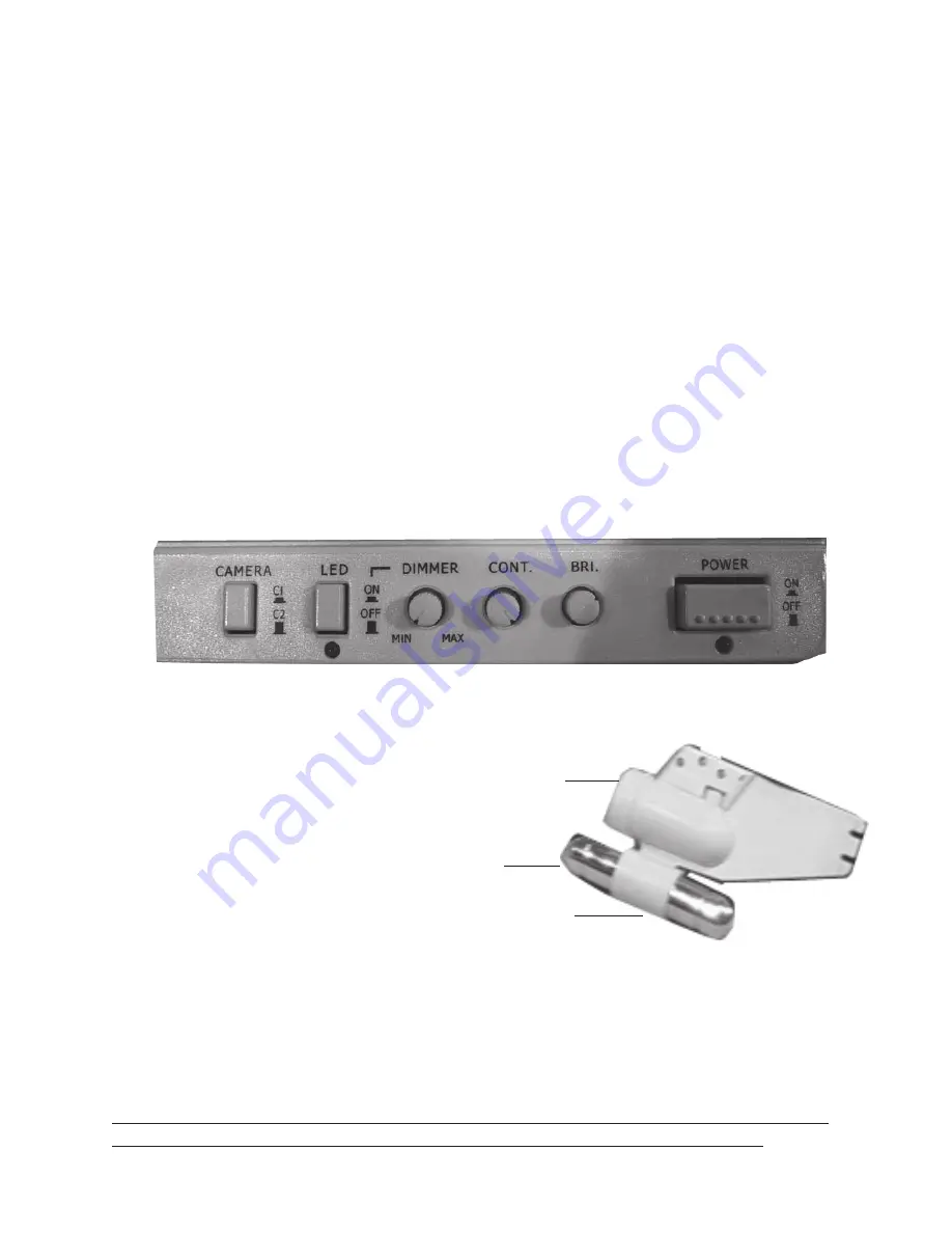
4. Turn on the POWER button on the front of the Monitor (2).  See FIGURE 3 below.

FIGURE 3

5. Push the Camera button (above) in, if using the C1 Camera input, and leave it out if using

the C2 input. You should see an image on the Monitor (2).
If not, recheck your connections.

Note:  The Ballast (see FIGURE 4) can be

set so that the Camera (1) can be set to
have no angle, or angled slightly down
or up.  Slightly open the bracket on
the Camera (1) to tilt the Ballast.

6. Gently lower the Camera into the wa-

ter and reel out the 65 Foot Cable (3)
until it is at the appropriate depth.

7. Adjust the Brightness (BRI.) and Contrast

(CONT.) on the front of the Monitor (2).  See
FIGURE 3.  If additional light is needed, push on the (LED) switch on the front of the
Monitor (2).  You can dim the LED lights with the DIMMER switch.

8. When you are finished, remove the Camera (1) from the water, turn off the POWER switch

on the Monitor (2), disconnect the alligator clips on the Battery Cord (5) from the Battery
(4), and unplug the Battery Cord (5) from the Monitor (2).

Warning!! Always keep the Camera (1) and Battery (4) dry and protected from the
elements.  Never try to disassemble the Camera’s (1) waterproof housing.

 FIGURE 4

Camera (1)

Bracket

Ballast

Содержание 91309

Страница 1: ...te at http www harborfreight com Copyright 2004 by Harbor Freight Tools All rights reserved No portion of this manual or any artwork contained herein may be reproduced in any shape or form without the express written consent of Harbor Freight Tools For technical questions and replacement parts please call 1 800 444 3353 91309 ...

Страница 2: ...re certain applications for which this product was designed Do not modify this product and do not use this product for a purpose for which it was not intended 6 Dress properly Do not wear loose clothing or jewelry as they can be caught in cables Protective electrically non conductive clothes and non skid footwear are recommended when working Wear restrictive hair covering to contain long hair 7 Us...

Страница 3: ...anty Only use accessories intended for use with this product Approved accessories are available from Harbor Freight Tools 14 Do not operate product if under the influence of alcohol or drugs Read warning labels if taking prescription medicine to determine if your judgment or reflexes are impaired while taking drugs If there is any doubt do not operate the product 15 Maintenance For your safety ser...

Страница 4: ...ping will cause acid to leak If acid leaks on you immediately wash off the acid with cold water Seek medical attention immediately 7 Always keep the RED terminal on the Battery 4 disconnected unless the system is being used When connected it will constantly drain the Battery 4 Operation Connecting the system Note This is a 12 Volt DC system and will not work on 24 Volt DC systems hooking the monit...

Страница 5: ... Camera switch on the back of the Monitor 2 to Camera 4 Turn on the POWER button on the front of the Monitor 2 See FIGURE 3 below FIGURE 3 5 Push the Camera button above in if using the C1 Camera input and leave it out if using the C2 input You should see an image on the Monitor 2 If not recheck your connections Note The Ballast see FIGURE 4 can be set so that the Camera 1 can be set to have no an...

Страница 6: ...d until the charge is complete Once the charge is complete the indicator will turn green Promptly unplug the unit from the power outlet and remove the clips from the terminals Do not overcharge the battery overcharging can result in damage to or acid leaking from the battery Never reverse the polarity when connecting the Battery 4 for charging it or running the system The Red terminal must be atta...

Страница 7: ...IRS TO THE PRODUCT OR THAT HE OR SHE IS QUALIFIED TO REPLACE ANY PARTS OF THE PRODUCT IN FACT THE MANUFAC TURER AND OR DISTRIBUTOR EXPRESSLY STATES THAT ALL REPAIRS AND PARTS RE PLACEMENTS SHOULD BE UNDERTAKEN BY CERTIFIED AND LICENSED TECHNICIANS AND NOT BY THE BUYER THE BUYER ASSUMES ALL RISK AND LIABILITY ARISING OUT OF HIS OR HER REPAIRS TO THE ORIGINAL PRODUCT OR REPLACEMENT PARTS THERETO OR ...

Отзывы: