


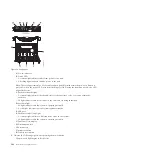


Note:
Specifying option 3 starts the Hardware Resource Concurrent Maintenance menu for the
selected packaging hardware resource.
k.
On the Hardware Resource Concurrent Maintenance display, start the Power off domain function
by pressing F9.
l.
Follow the online instructions to complete the power-off operation.
m.
If there is another I/O slot to process, return to step 5 on page 99. Otherwise, continue with step
10.
9.
Complete the following steps:
a.
Log in to the operating system with admin or service level authority. If you need assistance,
contact the system administrator.
b.
At the Linux command prompt, type
drslot_chrp_pci -r -s
io_slot_identifier
(where
io_slot_identifier
is the identifier string of the I/O slot), and press Enter.
c.
Follow the online instructions to complete the remove operation. However, do not perform the
steps to physically remove the adapter.
d.
If there is another I/O slot to process, return to step 5 on page 99. Otherwise, continue with step
10.
10.
If the system has a rear cover, remove or open it.
Important:
If the PCIe storage enclosure is connected to two systems, complete this step for each
system.
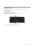
11.
Disconnect the PCIe cables that connect the PCIe storage enclosure by completing the following
steps:
a.
For each PCIe link that you recorded in step 4 on page 99, complete the following steps:
1)
Choose one of the following options:
v
If your system is managed by an HMC, complete the following steps:
a)
From the navigation bar, expand
Systems Management
.
b)
Click
Servers
.
c)
Select the server you are working with.
d)
In the Tasks area, expand
Hardware Information
.
e)
Click
PCIe Hardware Topology
.
v
If your system is not managed by an HMC, complete the following steps:
a)
Access the ASMI by using an authority level of administrator or authorized service
provider. For details about using the ASMI, see Managing the Advanced System
Management Interface (http://publib.boulder.ibm.com/infocenter/systems/scope/hw/
topic/p7hby/asmi.htm).
b)
In the ASMI navigation area, expand
System Configuration
.
c)
Click
PCIe Hardware Topology
.
2)
Select the PCIe link and click
Identify Indicators
.
3)
On the Identify Indicators display, select both locations and click
Activate LED
.
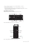
b.
Locate the PCIe storage enclosure that you are removing. Disconnect the PCIe cables from the
Enclosure RAID Modules (ERMs) in the PCIe storage enclosure. Use the identify indicators
activated in step 11a to assist in locating the PCIe storage enclosure and ERMs.
c.
Locate the PCIe connectors on the systems that connect to the PCIe storage enclosure. Disconnect
the PCIe cables from the systems. Use the identify indicators activated in step 11a to assist in
locating the PCIe connectors.
Important:
If the PCIe storage enclosure is connected to two systems, complete this step for each
system.
102
Enclosures and expansion units
Содержание Escala Power7 Series
Страница 1: ...Enclosures and expansion units ESCALA Power7 REFERENCE 86 A1 23FF 07 ...
Страница 2: ......
Страница 88: ...76 Enclosures and expansion units ...
Страница 146: ...134 Enclosures and expansion units ...
Страница 147: ......
Страница 148: ...Printed in USA ...


