


n.
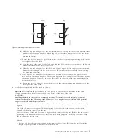
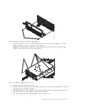
Use two M5 screws
(H)
to attach the retention bracket
(G)
to the rack on the right side.
o.
Insert a nut clip
(F)
at each mark on the left side of the rack.
p.
Use two M5 screws
(H)
to attach the retention bracket
(G)
to the rack on the left side.
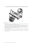
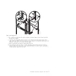
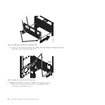
4.
Install the expansion unit onto the rails as follows:
a.
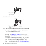
To remove the shipped cover from the rear of the expansion unit, remove the four thumb screws
that are used to secure it. Pull off the cover.
Note:
There are two thumb screws at the top of the cover and one on each side.
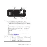
b.
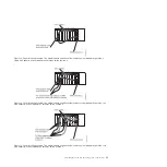
If the bezel is installed on the front of the system, remove it by completing the following steps:
1)
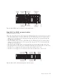
Remove the two M5 securing screws
(A)
as shown in Figure 6 on page 9.
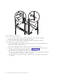
2)
Remove the service information holder from the slot in the bezel.
3)
Using the two blue touch points on each side of the expansion unit, pull the bezel straight out
to remove the bezel from the front of the expansion unit.
4)
Remove the two nut clips that were used to secure the bezel to the expansion unit from the
EIA flange.
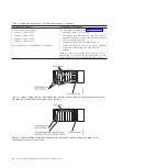
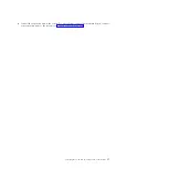
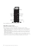
Figure 5. Installing the retention bracket
8
Power Systems: Installing the 58/02 and 58/77 expansion units
Содержание ESCALA Power7 5802
Страница 1: ...ESCALA Power7 Installing the 5802 and 5877 expansion units REFERENCE 86 A1 27FF 05...
Страница 2: ......
Страница 6: ...iv Power Systems Installing the 58 02 and 58 77 expansion units...
Страница 30: ...18 Power Systems Installing the 58 02 and 58 77 expansion units...
Страница 48: ...36 Power Systems Installing the 58 02 and 58 77 expansion units...


