


Item
Part No.
Description
595 TSL
S595 TSL
1
24729
595 TSL Mainframe 3.0 DIA. Lift
1
-
1
24737
S595 TSL Mainframe 3.0 DIA. Lift
-
1
2
24717
Quick Attach Left
1
1
3
24716
Quick Attach Right
1
1
4
112798
Cross Tube
1
1
5
108827
Pin Weldment
2
2
6
114296
Stand Tube
2
2
7
114303
Stand foot
2
2
8
113690
Link Spacer
2
2
9
110907
Stand Pin 0.625 diameter
2
2
10
12779
Hair Pin Clip
4
4
11
114186
Levelling Rod
1
1
12
112954
Pin 1.25 X 6.75 LG
2
2
13
112955
Pin 1.25 DIA X 5.00 LG
2
2
14
117371
Pin 1.25 DIA X 6.13 LG
2
2
15
114181
Levelling Tube
2
2
16
24242
Cross Tube Cover
1
1
17
Cylinder Bucket
18
Cylinder Lift
19
114252
Pin 1.25 DIA X 6.75 lg
4
4
20
81581
Hex Bolt 0.375 DIA X 2.5 LG
28
28
21
81669
Hex Bolt 0.625 DIA X 3.5
4
4
22
81592
Hex Nut 0.375 DIA
4
4
23
81344
Locknut 0.375 DIA
37
37
24
81967
Locknut 0.625 DIA
4
4
25
113691
Bushing 1.25 I.D. X 1.63 O.D x 0.75'' lg
8
8
26
81570
Flat Washer 0.375 DIA
4
4
27
113570
Bushing 1.25 I.D. X 1.63 O.D. x 1.88'' lg
4
4
28
113766
Bushing 1.25 I.D. x 1.50 O.D. x 1.38'' lg
20
20
29
114104
Pin 1.25 DIA X 7.48
4
4
30
113697
Pin 1.25 DIA X 8.63 LG
4
4
31
117372
Pin 1.25 DIA X 7.63 LG
2
2
32
114119
Link Weldment Left
2
2
33
114120
Link Weldment Right
2
2
34
81966
Locknut 0.50 DIA
2
2
35
84583
Grease Fitting 1/8 NPT Straight
2
2
36
FNH114039 Bolt Plate
1
1
37
FNH114040 Rod Guide
1
1
38
114097
Link Assembly 11.25
4
4
39
114101
Pivot Plate Left
1
1
40
113998
Pivot Plate Right
1
1
41
113995
Pin 1.25 DIA X 7.13 LG
2
2
42
813228
1/2" Wing nut (pl)
2
2
43
81637
1/2" Lock washer (Pl)
2
2
44
813356
Decal - Buhler Allied X 1.75
2
2
45
114132
Decal - TSL X 1.75
2
2
46
813358
Decal - True Self Levelling
2
2
47
113488
Decal - Quick Attach Instruction
2
2
48
52281-000 Bright Orange Scotchcal #72368
10ft
10ft
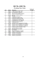
3.0 DIA. Lift Cyl.
595 TSL, S595 TSL
Main Frame Parts Table
25


