background image


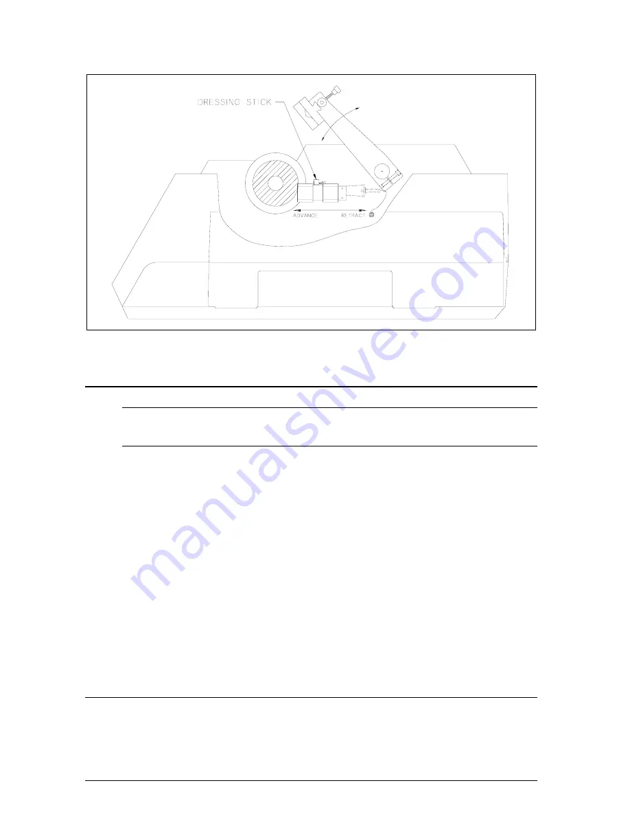
Figure 7

   Dressing Chuck and Blade Dressing 

Maintenance 

General Specification: 


1. 

Sound level is 77dBA maximum. 

Internal Coolant/Lubricant Recirculating System 

When Coolant/Lubricant is contaminated with abrasive residue or swarf, it 
should be discarded and replaced. 


1. 

To drain coolant; turn off unit, lift the hood, remove the blade and 
flanges. 

NOTE


Retract arm to the far left position. 

 2. 

DISCONNECT THE POWER CORDS FROM THE CABINET


3. 

Remove the Dressing Chuck Bracket and Coolant Assembly, and 
Screen. 


4. 

Lift the Coolant Tank at the handle and pull so that the tank slides 
horizontally. 


5. 

Thoroughly clean the Coolant Pump, Specimen Screen, Dressing 
Chuck and Coolant Tank. 


6. 

Slide the Coolant Tank back into the cabinet. 


7. 

Place the components back into the tank as shown in Figure 8. 
Connect the power cords into the correct connectors. 

Cleaning the Unit 

The ISOMET™ 2000 Precision Saw should be cleaned periodically to 
prevent build-up of cutting residue and cutting fluids. Exterior painted 
surfaces including the cutting chamber may be cleaned with non-abrasive 
household cleaners. 

11 

MA112480-20  

03/06/00 

Содержание ISOMET 2000

Страница 1: ...ISO 9001 Registered Company ISOMET 2000 Precision Saw MA112480 20 03 06 00 ...

Страница 2: ...nd 93 44 EEC according to the following standards 89 336 EEC and 92 231 EEC according to the following standards EN 292 PART 1 1991 EN 292 PART 2 1991 EN 60204 PART 1 1993 EN 50081 1 1992 EN 50082 1 1992 Position Engineering Manager Name Chuck Motley Signature Chuck Motley Date 11 28 95 This Manual is a custom generated document It includes all revisions relative to this specific Buehler item as o...

Страница 3: ... the Sample 6 Setting the Load 7 Checking and Adjusting Load 8 Cutting the Specimen 8 Blade Dressing 10 Pre Dressing 10 Dressing During the Cycle 10 Maintenance 11 General Specification 11 Internal Coolant Lubricant Recirculating System 11 Cleaning the Unit 11 ISOMET 2000 Precision Saw Application Guide 33 OPERATION AND MAINTENANCE INSTRUCTIONS BUEHLER ISOMET 2000 PRECISION SAW 1 MA112480 20 03 06...

Страница 4: ...ping instructions and include the following information Customer Purchase Order Number Buehler Invoice Number Date Serial Number and reason for return Unpacking Carefully unpack and check contents If any components are missing or damaged save the packing list and material and advise the carrier and BUEHLER of the discrepancy Assembly The ISOMET 2000 Precision Saw is shipped fully assembled A Dress...

Страница 5: ... End Cap Bushing from Drive Shaft 2 Install the Inner Flange on the Drive Shaft 3 Install the blade against the inner Flange 4 Slip on the Outer Flange and End Cap Bushing then hand tighten Thumb Screw to complete installation NOTE Before installation of a Wafering or Abrasive Blade the End Cap Bushing Screw and Flanges should be cleaned in a mild detergent solution to remove adherent particles fr...

Страница 6: ...sing the internal coolant system fill the coolant tank with the correct mixture of ISOCUT PLUS Cutting Fluid Concentrate and water The fluid level should be approximately 5 0 cm 2 deep or 4 liters ISOCUT PLUS Cutting Fluid has been formulated for optimum cooling and lubrication in medium and high speed cutting applications It is a water soluble concentrate which enhances the cooling properties of ...

Страница 7: ...breaker on the rear of the unit It should be in the I On position Press the POWER ON Button The green LED control light should energize as well as all the LED displays The unit is now ready for specimen loading Specimen Loading Several chucks are available to hold specimens of many different sizes and shapes See Accessories and Supplies Select the proper chuck for the particular application and at...

Страница 8: ...e rear of the support arm and adjust the arm as shown Check to be sure there is enough clearance so specimen can travel 25 6 mm past completion of the cut to allow for overtravel during the automatic stop cycle FORCES APPLIED NO EXTERNAL Figure 6A Support Arm Adjustment 3 Raise the Support Arm to a level approximately 1 cm above the blade CAUTION Do not allow the Specimen to contact the Blade whil...

Страница 9: ...utting cycle This is accomplished by pressing the LOAD INCREASE or DECREASE Button until the desired load is indicated on the Load LED Display NOTE The Display automatically sets to 100g when the unit is powered up The Load can be preset between 100g and 1000g in 10g increments NOTE The specimen must be loaded while the arm is in the raised position The ISOMET 2000 automatically tares the sample w...

Страница 10: ...ontrol Panel are used 1 Press the Lower Button on the Arm Section of the Panel until the Specimen is approximately 1 cm above the Blade 2 Close the cover WARNING The ISOMET 2000 Saw is designed to operate only with the cover closed This prevents manual feeding of sample materials or dressing sticks into the rotating blade which could result in personal injury and or blade damage Efforts to defeat ...

Страница 11: ...Figure 6 shows the factory set Arm position when the arm is raised to it s maximum relative to the various size Wafering Blades that may be used with the ISOMET 2000 Saw It is easy to see that there is a considerable distance for the Support Arm to travel before making contact with a four inch diameter blade The support arm should be lowered with the LOWER button until the specimen is about 1 cm f...

Страница 12: ...d result in serious injury or equipment damage Pre Dressing To Pre Dress the blade close the hood and press the dressing CHUCK RETRACT Button on the Control Panel Hold this button until the dressing chuck body retracts clear of the blade Insert the dressing stone in the clamp placing the edge of the stone approximately 1 16 behind the blade Secure the stone by tightening the thumbscrew Close the h...

Страница 13: ...ng Chuck Bracket and Coolant Assembly and Screen 4 Lift the Coolant Tank at the handle and pull so that the tank slides horizontally 5 Thoroughly clean the Coolant Pump Specimen Screen Dressing Chuck and Coolant Tank 6 Slide the Coolant Tank back into the cabinet 7 Place the components back into the tank as shown in Figure 8 Connect the power cords into the correct connectors Cleaning the Unit The...

Страница 14: ...The protective hood and touch pad control panel should be cleaned using mild soap and water applied with a soft cloth Figure 8 Tank Removal and Cleaning 12 MA112480 20 03 06 00 ...

Страница 15: ...Figure 9 Parts Diagram for ISOMET 2000 Precision Saw 13 MA112480 20 03 06 00 ...

Страница 16: ...Figure 10 Parts Diagram for ISOMET 2000 Precision Saw 14 MA112480 20 03 06 00 ...

Страница 17: ...Figure 11 Parts Diagram for ISOMET 2000 Precision Saw 15 MA112480 20 03 06 00 ...

Страница 18: ...Figure 12 Parts Diagram for ISOMET 2000 Precision Saw 16 MA112480 20 03 06 00 ...

Страница 19: ...Figure 13 Parts Diagram for ISOMET 2000 Precision Saw 17 MA112480 20 03 06 00 ...

Страница 20: ...Figure 14 Parts Diagram for ISOMET 2000 Precision Saw 18 MA112480 20 03 06 00 ...

Страница 21: ...Figure 15 Parts Diagram for ISOMET 2000 Precision Saw 19 MA112480 20 03 06 00 ...

Страница 22: ...Figure 16 Parts Diagram for ISOMET 2000 Precision Saw 20 MA112480 20 03 06 00 ...

Страница 23: ...Figure 17 Parts Diagram for ISOMET 2000 Precision Saw 21 MA112480 20 03 06 00 ...

Страница 24: ...Figure 18 Parts Diagram for ISOMET 2000 Precision Saw 22 MA112480 20 03 06 00 ...

Страница 25: ...Figure 19 Parts Diagram for ISOMET 2000 Precision Saw 23 MA112480 20 03 06 00 ...

Страница 26: ... 3 4 2 1 STRAIN GAUGE 2480S236 1 2 3 N C 1 2 4 8 7 6 5 1 2 2480S138 1 3 2 4 5 20 21 N C R10095 1 3 4 2 CIRCUIT BREAKER 1 2 N C 1 2 3 4 2480S139 5 2 3 4 1 2480S204 5 6 4 3 2480S217 2 3 1 J3103 BLK GRN RED 4 6 3 2 1 5 ARM UP POSITION 7 ARM DOWN POSITION MICROMETER HOME 5 1 2 3 4 85 264V 50 60HZ TM1 TM2 S S FG H N 2480S086 2480S097 FAN 2480S051 MICROMETER MOTOR AC INPUT L2 L1 GND 3 N C 2480S147 1 2 3...

Страница 27: ...Figure 21 Parts Diagram for ISOMET 2000 Precision Saw 25 MA112480 20 03 06 00 ...

Страница 28: ... 00 EA R1185 SCREW SET 10 32 3 8IN 2 00 EA R1273 SCREW SET 6 32 1 4IN SS 2 00 EA R1281 SCREW SET 8 32 1 8IN SS 2 00 EA R1293F SCREW SET 1 4 28 5 16IN SS NLC 1 00 EA R1625 SCREW 6 32 3 8IN SLT RD HD SS 2 00 EA R1652 SCREW 8 32 1 1 4IN SLT RDHD SS 4 00 EA R2004 SCREW 4 40 1 2IN SLT OV HD SS 2 00 EA R2408 SCREW 1 4 20 1 3 4IN HEX HD SS 4 00 EA R2858 SPEC PLATE BLANK NON C S A 1 00 EA R6106 CARTON 4X3...

Страница 29: ...0 EA R8902 CONNECTOR AC POWER 1 00 EA R8905 SCR MA 0 80 X 3 8 SOC ST BO 2 00 EA R8943 SCR SS 4 40 X 1 8 SS 2 00 EA R8944 SCR SS 4 40 X 1 4 SS 4 00 EA R8945 SCR MA M2 5 X 16 SOC SS 3 00 EA R8946 SCR MA 4 40 X 3 8 SS 16 00 EA R8972 ADAPTER 3 4 FGHT X 1 4 MNPT 1 00 EA R8975 CONN SNAP LOC M HOSE M PIPE 1 00 EA R8976 TUBING VINYL 3 4 ID X 1 OD 2 00 IN R8978 TEE 1 4 FNPT 1 00 EA R8979 CLAMP 1 NYLON HOSE...

Страница 30: ...KET 1 00 EA R9856 SUPPRESSOR 34 40 RIBBON CABLE 1 00 EA AK 207 ACCESSORY KIT F 112280 112480 1 00 EA 1180S72 NUT 6 32 KEPS 7 00 EA 1180S97 5 32 INCH HEX WR CD PL 1 00 EA 1180S133 MOLEX 3 PIN MALE PLUG 1 00 EA 1186S001 GLUE CHUCK 1 00 EA 1751P076 CIRCUIT BREAKER SPEED SENSOR 1 00 EA 1790S062 PLATE BILINGUAL CAUTION 2 00 EA 1950S054 SWITCH LIMIT TOP 1 00 EA 1950S056 SWITCH LIMIT BOTTOM 1 00 EA 2280S...

Страница 31: ... 00 EA 2480S083 SPECIMEN ARM ASSEMBLY 1 00 EA 2480S084 THUMB SCREW ASSEMBLY 1 00 EA 2480S085 MOTOR DRESSING CHUCK 1 00 EA 2480S086 DRESSING CHUCK ASSEMBLY 1 00 EA 2480S087 PCB HIGH VOLTAGE 1 00 EA 2480S096 THUMB SCREW ASSEMBLY 1 00 EA 2480S097 MIC SWITCH ASSEMBLY 1 00 EA 2480S114 CLAMP SINGLE SADDLE 0 00 EA 2480S115 CHUCK SINGLE SADDLE 0 00 EA 2480S135 CONNECTOR SPIGOT 1 00 EA 2480S138 CABLE OPER ...

Страница 32: ...CPU ANALOG INTERFACE 1 00 EA 2480S219 SCREW THUMB 1 00 EA 2480S221 SCREEN 125 HOLES POLYPROP 1 00 EA 2480S222 SPACER HINGE 3 00 EA 2480S226 BRACKET SPD SENSOR 1 00 EA 2480S227 PLATE SPEC ISOMET 2000 EC 1 00 EA 2480S228 SENSOR ASSEMBLY SPEED 1 00 EA 2480S229 CABINET UPPER ISOMET 2000 EC 1 00 EA 2480S230 CABINET LOWER ISOMET 2000 EC 1 00 EA 2480S231 HARNESS CIRC BKR EMI FILTER 1 00 EA 2480S232 PCB O...

Страница 33: ...mm Series 15 LC Diamond low concentration 11 4254 012 0 3 mm 11 4255 015 0 4 mm 11 4276 020 0 5 mm 11 4277 025 0 64 mm Series 10 LC Diamond low concentration 11 4285 015 0 4 mm 11 4287 020 0 5 mm Series 5 LC Diamond low concentration 11 4295 015 0 4 mm ISOCUT Wafering Blades Low concentration 11 4264 012 0 3 mm 11 4265 015 0 4 mm 11 4266 020 0 5 mm 11 4267 025 0 6 mm Abrasive Cut off Wheels For fe...

Страница 34: ... x 1 7 8 L 29mm x 46 mm capacity for thin sectioning of specimens mounted to a glass slide 11 2485 IRREGULAR SPECIMEN CHUCK for irregularly shaped samples 11 2486 THIN SECTIONS AND WAFER CHUCK for wafers single crystals and thin sections 11 2487 SINGLE SADDLE CHUCK 1 1 4 32 mm diameter capacity for bar and tube stock 11 2488 GLASS SLIDE CHUCK 2 W x 3 L 51 mm x 76 mm capacity for thin sectioning of...

Страница 35: ...iamond 2500 rpm 500 grams Tungsten carbide 6 cobalt binder WC Series 15 HC diamond 4000 rpm 800 grams Tungsten carbide 25 cobalt binder WC Series 15 HC diamond 4500 rpm 900 grams High purity fused silica SiO2 Series 10 LC diamond 1500 rpm 300 grams Extruded alumina Al2O3 Series 10 LC diamond 2500 rpm 500 grams Aluminum nitride AlN Series 10 LC diamond 3000 rpm 600 grams Nickel zinc ferrite Mo Fe2O...

Страница 36: ...NOTES 34 MA112480 20 03 06 00 ...

Отзывы: