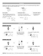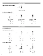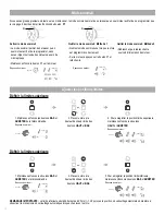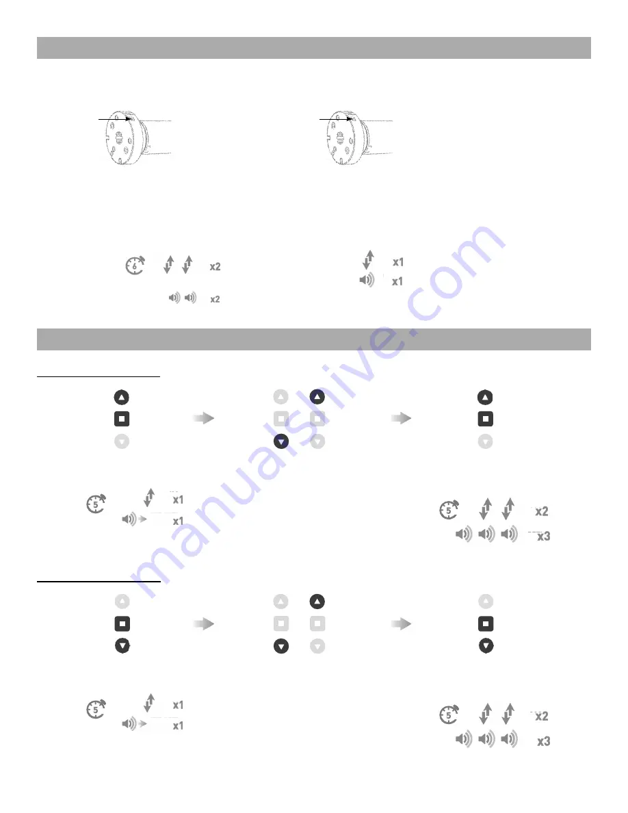
Adjusting Upper Limit
IMPORTANT:
The bottom limit should be set ~1.38 in. (35mm) below the Ultra-Lock to disengage the auto lock mechanism when the shade is raised.
2. Move shade to the desired
highest position by pressing
the
UP
or
Down
button
If multiple motors are grouped on a single channel, Sleep Mode may be used to put all but 1 motor to sleep, allowing programming of just the one
motor that remains “Awake”. See page 9 for detailed
P1
functions.
Motor Response:
Motor Response:
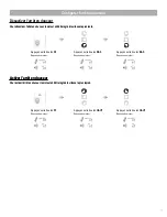
Enter Sleep Mode
• Sleep mode is utilized to prevent a motor from
incorrect configuration during other motor setup.
• Hold P1 button on the motor head.
Exit Sleep Mode: Method 1
• Exit sleep mode once the shade is ready.
• Press and release P1 button on the motor head.
Exit Sleep Mode: Method 2
• Remove power and then
re-power the motor.
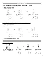
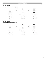
Adjusting Lower Limit
1. Hold
DOWN
and
STOP
on controller
Motor Response:
3. To save lower limit, hold
DOWN
and
STOP
Motor Response:
1. Hold
UP
and
STOP
on controller
Motor Response:
2. Move shade to the desired
lowest position by pressing
the
UP
or
Down
button
3. To save upper limit, hold
UP
and
STOP
Motor Response:
4
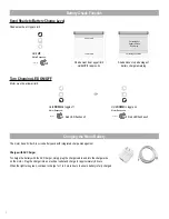
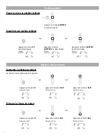
Set Limits
To save upper limit, hold
UP
and
STOP
.
Cycle shade up and down prior to setting limits to settle fabric
Move shade to the desired highest or lowest position by
pressing the
UP
or
DOWN
buttons on controller.
Motor Response
OR
Approx.
Move shade to the desired highest or lowest position
by pressing the
UP
or
DOWN
buttons
on controller.
OR
After setting limits, motor will automatically exit from initial set-up mode.
To save lower limit, hold
DOWN
and
STOP
.
Motor Response
Approx
.
IMPORTANT
IMPORTANT
.
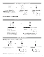
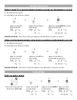
Pair motor with controller
Check motor direction
Consult user manual for your
controller for information on
selecting channel.
Damage to shade may occur when operating motor prior to
setting limits. Attention should be given.
Reversing motor direction using this method is only possible
during initial set-up
Hold
P1
button on
motor head.
To check travel direction of shade, press
UP
or
DOWN
on controller.
Quick Press
= Step
Long Press
= Continuous Travel
To reverse shade direction, hold both
UP
and
DOWN
.
Until the motor responds.
Select channel on
controller.
Hold
STOP
on
controller.
Approx.
Approx.
Motor Response
Motor Response
Motor Response
Motor is now in step mode and ready for setting limits
IMPORTANT
IMPORTANT
IMPORTANT
5
INITIAL SET UP
OR
9
SLEEP MODE
Enter Sleep Mode
Sleep mode is utilized to
prevent a motor from incorrect
configuration during other
motor setup.
Hold
P1
button on the motor
head
If multiple motors are grouped on a single channel, Sleep Mode may be used to put all but 1 motor to sleep,
allowing programming of just the one motor that remains “Awake”. See page 6 for detailed
P1
functions.
Exit Sleep Mode: Method 1
Exit sleep mode once the shade
is ready.
Press and release
P1
button on
the motor head
Exit Sleep Mode: Method 2
Remove power and then
re-power the motor.
Motor Response
Motor Response
14 SLEEP MODE
Approx.
JOG
BEEP
.
Pair motor with controller
Check motor direction
Consult user manual for your
controller for information on
selecting channel.
Damage to shade may occur when operating motor prior to
setting limits. Attention should be given.
Reversing motor direction using this method is only possible
during initial set-up
Hold
P1
button on
motor head.
To check travel direction of shade, press
UP
or
DOWN
on controller.
Quick Press
= Step
Long Press
= Continuous Travel
To reverse shade direction, hold both
UP
and
DOWN
.
Until the motor responds.
Select channel on
controller.
Hold
STOP
on
controller.
Approx.
Approx.
Motor Response
Motor Response
Motor Response
Motor is now in step mode and ready for setting limits
IMPORTANT
IMPORTANT
IMPORTANT
5
INITIAL SET UP
OR
.
Pair motor with controller
Check motor direction
Consult user manual for your
controller for information on
selecting channel.
Damage to shade may occur when operating motor prior to
setting limits. Attention should be given.
Reversing motor direction using this method is only possible
during initial set-up
Hold
P1
button on
motor head.
To check travel direction of shade, press
UP
or
DOWN
on controller.
Quick Press
= Step
Long Press
= Continuous Travel
To reverse shade direction, hold both
UP
and
DOWN
.
Until the motor responds.
Select channel on
controller.
Hold
STOP
on
controller.
Approx.
Approx.
Motor Response
Motor Response
Motor Response
Motor is now in step mode and ready for setting limits
IMPORTANT
IMPORTANT
IMPORTANT
5
INITIAL SET UP
OR
EXT. BEEP
JOG
Set Limits
To save upper limit, hold
UP
and
STOP
.
Cycle shade up and down prior to setting limits to settle fabric
Move shade to the desired highest or lowest position by
pressing the
UP
or
DOWN
buttons on controller.
Motor Response
OR
Approx.
Move shade to the desired highest or lowest position
by pressing the
UP
or
DOWN
buttons
on controller.
OR
After setting limits, motor will automatically exit from initial set-up mode.
To save lower limit, hold
DOWN
and
STOP
.
Motor Response
Approx
.
IMPORTANT
IMPORTANT
JOG
BEEP
Set Limits
To save upper limit, hold
UP
and
STOP
.
Cycle shade up and down prior to setting limits to settle fabric
Move shade to the desired highest or lowest position by
pressing the
UP
or
DOWN
buttons on controller.
Motor Response
OR
Approx.
Move shade to the desired highest or lowest position
by pressing the
UP
or
DOWN
buttons
on controller.
OR
After setting limits, motor will automatically exit from initial set-up mode.
To save lower limit, hold
DOWN
and
STOP
.
Motor Response
Approx
.
IMPORTANT
IMPORTANT
SECS
Approx.
Se
t L
imits
To s
ave up
per
lim
it, hol
d
UP
and
STOP
.
Cyc
le s
hade up and dow
n prior
to s
etting l
imi
ts t
o se
ttle f
abric
Move
shade
to th
e de
sired
highes
t or
low
est pos
ition
by
pres
sing
the
UP
or
DOW
N
butto
ns on
cont
roll
er.
Mot
or R
espo
nse
OR
Appr
ox.
Move
shade
to th
e des
ired
hig
hest or
low
est pos
ition
by
pres
sing
the
UP
or
DOW
N
butt
ons
on cont
roll
er.
OR
Afte
r se
tting
lim
its,
mot
or w
ill aut
omat
ica
lly
exit
fro
m in
itial
set
-up
mode.
To
sav
e low
er lim
it, hol
d
DOW
N
and
STOP
.
Mot
or R
espo
nse
Appr
ox
.
IM
PORT
ANT
IM
PORT
ANT
.
Pair motor with controller
Check motor direction
Consult user manual for your
controller for information on
selecting channel.
Damage to shade may occur when operating motor prior to
setting limits. Attention should be given.
Reversing motor direction using this method is only possible
during initial set-up
Hold
P1
button on
motor head.
To check travel direction of shade, press
UP
or
DOWN
on controller.
Quick Press
= Step
Long Press
= Continuous Travel
To reverse shade direction, hold both
UP
and
DOWN
.
Until the motor responds.
Select channel on
controller.
Hold
STOP
on
controller.
Approx.
Approx.
Motor Response
Motor Response
Motor Response
Motor is now in step mode and ready for setting limits
IMPORTANT
IMPORTANT
IMPORTANT
5
INITIAL SET UP
OR
.
Pair motor with controller
Check motor direction
Consult user manual for your
controller for information on
selecting channel.
Damage to shade may occur when operating motor prior to
setting limits. Attention should be given.
Reversing motor direction using this method is only possible
during initial set-up
Hold
P1
button on
motor head.
To check travel direction of shade, press
UP
or
DOWN
on controller.
Quick Press
= Step
Long Press
= Continuous Travel
To reverse shade direction, hold both
UP
and
DOWN
.
Until the motor responds.
Select channel on
controller.
Hold
STOP
on
controller.
Approx.
Approx.
Motor Response
Motor Response
Motor Response
Motor is now in step mode and ready for setting limits
IMPORTANT
IMPORTANT
IMPORTANT
5
INITIAL SET UP
OR
EXT. BEEP
JOG
Se
t L
imits
To s
ave up
per
lim
it, hol
d
UP
and
STOP
.
Cyc
le s
hade up and dow
n prior
to s
etting l
imi
ts t
o se
ttle f
abric
Move
shade
to th
e de
sired
highes
t or
low
est pos
ition
by
pres
sing
the
UP
or
DOW
N
butto
ns on
cont
roll
er.
Mot
or R
espo
nse
OR
Appr
ox.
Move
shade
to th
e des
ired
hig
hest or
low
est pos
ition
by
pres
sing
the
UP
or
DOW
N
butt
ons
on cont
roll
er.
OR
Afte
r se
tting
lim
its,
mot
or w
ill aut
omat
ica
lly
exit
fro
m in
itial
set
-up
mode.
To
sav
e low
er lim
it, hol
d
DOW
N
and
STOP
.
Mot
or R
espo
nse
Appr
ox
.
IM
PORT
ANT
IM
PORT
ANT
Set Limits
To save upper limit, hold
UP
and
STOP
.
Cycle shade up and down prior to setting limits to settle fabric
Move shade to the desired highest or lowest position by
pressing the
UP
or
DOWN
buttons on controller.
Motor Response
OR
Approx.
Move shade to the desired highest or lowest position
by pressing the
UP
or
DOWN
buttons
on controller.
OR
After setting limits, motor will automatically exit from initial set-up mode.
To save lower limit, hold
DOWN
and
STOP
.
Motor Response
Approx
.
IMPORTANT
IMPORTANT
JOG
BEEP
Set Limits
To save upper limit, hold
UP
and
STOP
.
Cycle shade up and down prior to setting limits to settle fabric
Move shade to the desired highest or lowest position by
pressing the
UP
or
DOWN
buttons on controller.
Motor Response
OR
Approx.
Move shade to the desired highest or lowest position
by pressing the
UP
or
DOWN
buttons
on controller.
OR
After setting limits, motor will automatically exit from initial set-up mode.
To save lower limit, hold
DOWN
and
STOP
.
Motor Response
Approx
.
IMPORTANT
IMPORTANT
SECS
Approx.
P1
P1
9
SLEEP MODE
Enter Sleep Mode
Sleep mode is utilized to
prevent a motor from incorrect
configuration during other
motor setup.
Hold
P1
button on the motor
head
If multiple motors are grouped on a single channel, Sleep Mode may be used to put all but 1 motor to sleep,
allowing programming of just the one motor that remains “Awake”. See page 6 for detailed
P1
functions.
Exit Sleep Mode: Method 1
Exit sleep mode once the shade
is ready.
Press and release
P1
button on
the motor head
Exit Sleep Mode: Method 2
Remove power and then
re-power the motor.
Motor Response
Motor Response
14 SLEEP MODE
Approx.
SECS
Approx.
RELAPSE P1
JOG
BEEP
Set Limits
To save upper limit, hold
UP
and
STOP
.
Cycle shade up and down prior to setting limits to settle fabric
Move shade to the desired highest or lowest position by
pressing the
UP
or
DOWN
buttons on controller.
Motor Response
OR
Approx.
Move shade to the desired highest or lowest position
by pressing the
UP
or
DOWN
buttons
on controller.
OR
After setting limits, motor will automatically exit from initial set-up mode.
To save lower limit, hold
DOWN
and
STOP
.
Motor Response
Approx
.
IMPORTANT
IMPORTANT
SECS
Approx.
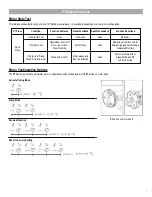
Using P2 Button on existing controller to add a new controller or channel
Using a pre-existing controller to add or delete a controller or channel
A
= Existing controller or channel (to keep)
B
= Controller or channel to add or remove
A
= Existing controller or channel (to keep)
B
= Controller or channel to add or remove
Press
P2
on
controller
A
.
Press
P2
on
controller
A
.
Press
P2
on
controller
A
.
Press
P2
on
controller
A
.
Press
P2
on the
controller
B
to remove
it.
Press
STOP
on an new
controller to add it.
Motor Response
Motor Response
Motor Response
Motor Response
Motor Response
Motor Response
7
CONTROLLERS AND CHANNELS
Consult user manual for your controller or sensor
Consult user manual for your controller or sensor
IMPORTANT
IMPORTANT
Adjusting Limits
Sleep Mode


