background image

Keycode Setting 


SMART MATRIX TWIST 

- 2-19 -


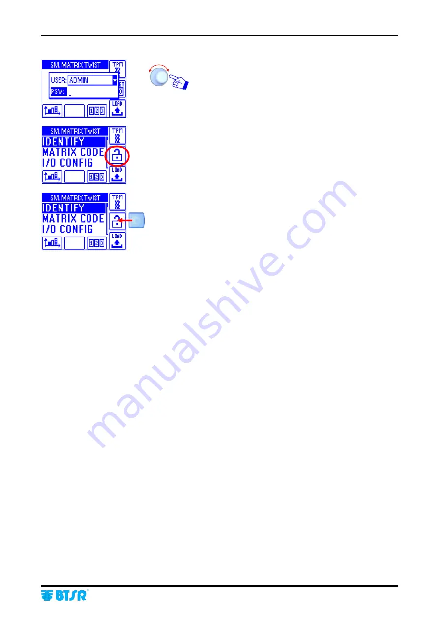
When you try to access a password-protected function, the following prompt will appear:


Choose the user name and set the password to access the 
selected function.


The flashing padlock symbol indicates that all access to Smart Matrix 
TWIST function took place entering a valid password (

login

). 

If no operation is carried out within 90 seconds, then the padlock symbol 
will disappear and you will be requested to type again the password to 
access the protected functions. 


Pressing the button associated with the padlock symbol, will force an 
immediate logout, without waiting for 90 seconds (

the padlock symbol will 

disappear

). 


How to Disable the Keycode Function


To disable the password protection function, you will have to clear all the set users (

using the CLR button

and clear the Administrator password (

turning the selector and clicking until all the password characters will 

be replaced by blanks

). 


Password Protected Functions


…


SETUP MENU

 Access 

to 

SETUP

 menu function 

…


STYLE MODIFY

 Access 

to 

STYLE 

menu function 

…


STYLE LOAD

 Access 

to 

LOAD 

menu function 

…


RESET COUNTERS


Counters reset (

with 

RESET ALL

 and 

RESET DOFF

 buttons within the 

Error Counter Display screen

…


SENSORS ON/OFF


Sensor activation/deactivation (

with the 

ON/OFF

 button within the Sensors 

Histogram


The user may access exclusively the functions selected (

;

) within the 

FEATURES

 window. 


Содержание SMART MATRIX TWIST

Страница 1: ...SMART MATRIX TWIST Operating Manual ENGLISH Rev 1 2 January 2012 ...

Страница 2: ...y time the contents of this Manual without notice For any technical or commercial problem please contact your local BTSR dealer or call directly BTSR Customer Service Center We will be glad to meet your needs Thank you for your trust and good job The product described herein is compliant with the requirements of EMC Directive 2004 108 EC and of Low Voltage Directive 2006 95 EC All BTSR products ar...

Страница 3: ...Introduction i ...

Страница 4: ......

Страница 5: ... User Friendly graphic interface allows you to quickly and intuitively program all the operating parameters of IS3F TTS IS3W TTS sensors in addition it provides a real time monitoring of sensors behaviour and production efficiency The SMART MATRIX TWIST system represents an alternative to the PC LINK TWIST BTSR solution which allows you to monitor the production program the IS3F TTS IS3W TTS senso...

Страница 6: ...data errors display facilities Section 3 describes the main characteristics and performances of the various system components IS3F TTS IS3W TTS sensors SM DIN TWIST modules power supplies interface modules etc Symbols Used This symbol is used to point out notes warnings and other important information IS3 Within this manual the IS3F TTS and IS3W TTS sensors used for SMART MATRIX TWIST application ...

Страница 7: ...hout the Display Windows 2 2 Immediate Function Activation through the SMART MATRIX Buttons 2 7 Interpretation of Operating Screens 2 8 SMART MATRIX TWIST Menu Structure 2 9 Sensor Configuration and Numbering 2 10 Smart Matrix Code 2 13 Output Configuration on SM DIN Smart Matrix 2 14 Keycode Setting 2 17 Communication Test 2 20 Sensors Test 2 21 Service Functions 2 22 MATRIX LCD Adjustment 2 27 I...

Страница 8: ...Table of Contents SMART MATRIX TWIST iv Page intentionally left blank ...

Страница 9: ...Connections and Electrical Interface 1 ...

Страница 10: ......

Страница 11: ...sensors Connection To update the firmware on SM DIN Boards you must Disconnect cable from Smart Matrix PC IN connector Disconnect cable from 1st SM DIN Board SM IN connector Connect cable to connector of 1st SM DIN Board Prior to operate the SMART MATRIX terminal make sure you have programmed the communication speed on all the SM DIN TWIST as well as on CV232 485 9 module For more details please r...

Страница 12: ...sor connection can be carried out directly on SM DIN Boards max 64 sensors per Board or by means of an optional ACT POWER module max 100 sensors per module The following diagram shows the direct connection of IS3F TTS Sensors to a SM DIN Board as well as the connection between SM DIN Boards and SMART MATRIX You can connect IS3F TTS and IS3W TTS sensors together on the same line Max 64 sensors IS3F...

Страница 13: ...ST 1 3 The following diagram shows the connection of IS3F TTS Sensors to the ACT POWER module the connection between ACT POWER module and SM DIN Board and between SM DIN Board and SMART MATRIX terminal Max 100 sensors IS3F TTS 6 lines max 20 sensors per line ...

Страница 14: ...sor connection can be carried out directly on SM DIN Boards max 64 sensors per Board or by means of an optional ACT POWER module max 100 sensors per module The following diagram shows the direct connection of IS3W TTS Sensors to a SM DIN Board as well as the connection between SM DIN Boards and SMART MATRIX You can connect IS3F TTS and IS3W TTS sensors together on the same line Max 54 sensors IS3W...

Страница 15: ...ST 1 5 The following diagram shows the connection of IS3W TTS Sensors to the ACT POWER module the connection between ACT POWER module and SM DIN Board and between SM DIN Board and SMART MATRIX terminal Max 100 sensors IS3W TTS 6 lines max 17 sensors per line ...

Страница 16: ...ws the electrical interface pin assignment of SM DIN Board The sensor interface is shown on page 1 8 Recommended power supply 24 Vdc with PSU 20 AS ASM PSU 20AS three phase power supply 400 Vac PSU 20ASM single phase power supply 230 Vac Machine Interface INPUT Machine Interface OUTPUT Power Supply ...

Страница 17: ...ER System Power Supply On systems including both SM DIN modules and ACT POWER modules the power supply is provided on the ACT POWER module POWER connector while the SM DIN module power supply is provided by the SM DIN ACT POWER connection cable as shown on next figure ...

Страница 18: ...Max 64 IS3F TTS sensors or 54 IS3W TTS sensors numbered with the Identify function Setup menu SM DIN Max 100 IS3F TTS or IS3W TTS sensors numbered with the Identify function Setup menu ACT Power optional Drop line 1 Sensors Drop line 2 Sensors Drop line 3 Sensors Drop line 4 Sensors Drop line 6 Sensors Drop line 5 Sensors Drop line 4 Sensors Drop line 3 Sensors Drop line 2 Sensors Drop line 1 Sens...

Страница 19: ...e LV green Led shows a double flashing communication speed on CV232 485 9 115 Kbps If necessary press the small P button SMART MATRIX Terminal Technical Characteristics Power supply voltage 24 VDC 10 Current absorption 100 mA Max Protection fuse SMART MATRIX 1 5 A Protection fuse Sensor power supply 1 5 A 0 24 VDC VIL Max 1 2 VDC Inputs VIH Min 5 VDC Operating temperature range 10 60 C Storage tem...

Страница 20: ...1 to 250 sec Signalling With integrated LED With integrated LED Dimensions 36 8x25x15 mm 36 3x25x10 mm Communication bus One wire One wire Storage temperature range 25 85 C 25 85 C Temperature range 10 60 C 10 60 C SM DIN TWIST The SM DIN TWIST Boards represent the interface between IS3 sensors and SMART MATRIX Terminal On each SM DIN TWIST Board it is necessary to setup 2 essential parameters P01...

Страница 21: ...pply voltage 24 VDC Current absorption sum of all 6 channels 9A Max Max current absorbed by each channel 1 5A Max Operating temperature range 10 60 C Storage temperature range 25 85 C Overall dimensions 138 5x124x35 mm The following figure shows the electrical interface pin assignment of ACT POWER module ...

Страница 22: ...ID and Baudrate SM DIN Configuration SMART MATRIX TWIST 1 12 ID and Transmission Speed Configuration on Each SM DIN Board P01 P02 Parameters ...

Страница 23: ...erate on different machine points The SM DIN Boards and the sensors are physically connected to one terminal Master while the second terminal Slave acts exclusively as a repeater The SLAVE terminal identification code must be equal to the MASTER terminal identification code 1 Example MASTER code 5 SLAVE code 6 The MASTER SLAVE connection must be carried out as shown on the following figure For mor...

Страница 24: ...IX TWIST 1 14 Example of Plant Layout The following figure shows a configuration example with 1 SMART MATRIX TWIST terminal 2 SM DIN TWIST Board 4 IS3W TTS sensors for Board 1 and 4 IS3F TTS sensors for Board 2 Power supply unit PSU20AS ...

Страница 25: ...Operating Instructions 2 ...

Страница 26: ......

Страница 27: ... particular functions increment decrement speed up shortcuts C Multi function rotary selector How to Use the Rotary Selector The selector provides both pointing and data entry and or confirmation function Pointing Turn the selector to select a menu item function parameter within the configuration screens etc or to increase decrease a data field value Rapid click to confirm the selection or the set...

Страница 28: ...RT MATRIX terminal can be carried out using exclusively the multi function Rotary Selector through a navigation technique based upon Pointing Selecting and Value Setting actions The following example explains this navigation technique The example refers to the Input Output Configuration function on SM DIN SMART MATRIX which makes use of 4 windows IN OUT CV PRX 1 Name label of currently selected wi...

Страница 29: ... to Select the pointed item The field name will be shown in reverse and the symbols appear to the right of the field value Example START field selected reverse Turn the selector to either clockwise or counter clockwise direction to select either NO Normally Open or NC Normally Closed Once you have set the desired value click to confirm Now the START field will no more be shown in reverse Turn the ...

Страница 30: ...rent window IN and click to select it Example Î Turn the selector to Point in sequence the various windows IN OUT CV PRX Î Î Î Click to select the desired window thus enabling access to the relevant parameters Select the desired parameter as explained on previous paragraph 1 Navigation inside the Selected Window IN ...

Страница 31: ...ovide the following functions It allows selecting in sequence the set of capital letters small letters and numbers graphic symbols DEFAULT STYLE NAME It allows clearing the character to the left of cursor within the STYLE NAME field It allows leaving the string entering function To enter the Style Name e g STYLE1 operate as follows Select in sequence the S T Y L E keys the entered characters will ...

Страница 32: ...T to return to menu without saving 5 Resolution of Increment Decrement Values To speed up the increment decrement of programmable numeric fields you may use the buttons while turning the selector The available resolutions indicated by a small label in reverse on the left side of the field are the following Only selector Î x1 Increment decrement by 1 Î x10 Increment decrement by 10 Î x100 Increment...

Страница 33: ...ailed explanation of the various function will be provided on next paragraphs The following examples are only provided to summarize the Button Function association Within some configuration parameter setting functions the B1 B6 buttons may also perform a shortcut function which will be explained each time Immediate function activation buttons B1 Sensor Histogram Î B2 Not used B3 Error Counters Î B...

Страница 34: ... Operation SMART MATRIX TWIST 2 8 Interpretation of Operating Screens System running No error detected 7 active sensors out of 7 Efficiency 100 7 sensors detected the Twist L error 0 active sensors out of 7 Efficiency 0 ...

Страница 35: ...status In the description of the various functions the following graphic symbols will be used Select the desired option and click to confirm Press and hold down the button 3 sec to return to previous menu and or to activate the data saving function Error Error indication Main Menu Style Configuration Error Styles Scanning System Configuration Run Status ...

Страница 36: ...Set the number of SM DIN TWIST Boards used 1 8 in the example 1 Set the number of the 1st Board FIRST BOARD Always set FIRST BOARD 1 Point the symbol of 1st Board Select the field indicating the number of sensors connected to Board 1 default 0 Set the number of sensors actually connected to Board 1 e g 7 and confirm Point the symbol of 2nd Board and so on for all the Boards used Once you have conf...

Страница 37: ...sensor identification The example shown indicates that the numbering identification of the 7 configured sensors is going to start The flashing reference indicates the first sensor to be identified A1 The display of all Boards will show The green led will flash on all sensors Skim the touch light of the sensor you want to assign the identifier A1 the green led of the sensor will turn from flashing ...

Страница 38: ...Select the coordinates of the sensor to be re numbered See Note 1 Skim the touch light of the relevant sensor The sensor s led changes from flashing green to red To quit the identification procedure after the sensor re numbering EXIT to return to configuration menu Note 1 To select the coordinates of the sensor you wan to renumber e g A4 operate as follows Turn the selector to select the desired s...

Страница 39: ...terminal the SLAVE terminal identification code must be equal to the MASTER terminal identification code 1 For more details about the MASTER SLAVE connection please refer to the SMART MATRIX Master SMART MATRIX Slave Connection paragraph on Section 1 Enter the SETUP menu Select MATRIX CODE Choose the SMART MATRIX identification code and activate the save function SAVE to save the choice BACK to re...

Страница 40: ...nal as normally open NO or normally closed NC contact Enter the SETUP menu Select I O CONFIG Select BOARDS Turn the selector to point in sequence each field of the window IN START EXT 3 EXT 2 PRX The frame indicates the Pointed field Click to select the pointed item The field name will be highlighted reverse Example START field selected reverse Turn the selector to choose the polarity of START sig...

Страница 41: ...te 1 on next page Then select the PRX window Set the yarn amount expressed in mm processed by the machine in the interval between two PRX pulses 1 10000 This value is used by the system to determine the yarn collection speed when a synchronism signal is provided and the Auto speed option is chosen in the Style creation stage See Note 1 on next page To activate the saving function once you have set...

Страница 42: ...ng EXIT to return to menu Note 1 The value increment decrement resolution can be changed using the direct activation buttons B1 B2 B3 Setting example ACQ TIME No push button pressed resolution x1 increment decrement by 1 Resolution x10 increment decrement by 10 Resolution x100 increment decrement by 100 Resolution x1000 increment decrement by 1000 ...

Страница 43: ...d for the administration The administrator can create new users associate an identification password to each user and configure the list of accessible menus and options he can also remove clear users and change the list of accessible menus and options You cannot set two users with the same name or with the same password Enter the SETUP menu Select KEY CODE How to Set the Administrator Password Pre...

Страница 44: ...ET COUNTERS SENSORS ON OFF To confirm and save the settings The new user will appear in the list of KEYCODE EDITOR screen User name and password can be set character by character turning the selector and clicking to confirm you may set numeric and alphabetic characters Clear a User Press CLR button to remove the selected user from the list Change Configuration Press EDIT button to edit change the ...

Страница 45: ...ogout without waiting for 90 seconds the padlock symbol will disappear How to Disable the Keycode Function To disable the password protection function you will have to clear all the set users using the CLR button and clear the Administrator password turning the selector and clicking until all the password characters will be replaced by blanks Password Protected Functions SETUP MENU Access to SETUP...

Страница 46: ...ions Select GLOBAL global communication efficiency or SINGLE communication efficiency with the individual Board Number of sensors on which communication errors occurred DEV IN ERROR and total number of transmissions repeated as a result of detected errors TOTAL RETRY A maximum of 5 transmissions are repeated for each board Global efficiency index Like for GLOBAL option but referred to the selected...

Страница 47: ...sors Test Enter the SETUP menu Select TEST COM Select SENSOR TEST Turn the selector and check that only the sensor installed at Side Position and Section coordinates indicated on Smart Matrix display is blinking red SETUP TEST COM SENSOR TEST ...

Страница 48: ...ENS UPG Select the sensor s for which you want to upgrade the firmware In the from space you may choose the range of sensors whose firmware shall be upgraded POSITION n to m or SECTION n to m pointing and confirming the relevant fields In the on side space you may specify all machine sides ALL or only the desired side A or B Examples to upgrade only the sensor No 3 of side B set from POSITION 3 to...

Страница 49: ...es the percentage of already upgraded sensors At the end of upgrading process the bar will show Upgrade completed Note At any time you can interrupt the upgrading process pressing the STOP button return to SERVICE menu How to Read the Parameters Currently Programmed on Sensors Enter the SETUP menu Select SERVICE Select SENS READ SETUP SERVICE SENS READ ...

Страница 50: ...pe of selected sensor Firmware revision of A1 sensor Values setup for the article style currently loaded on A1 sensor To return to SERVICE menu For more details about the meaning of each parameter please refer to Section 3 Characteristics of IS3 Sensors For more details about the parameter setting procedures please refer to STYLE menu ...

Страница 51: ...dicated on the header in the example 1 SM DIN hw sw revision levels and IS3 firmware revision The IS3 firmware revision is not that actually read from the sensor but rather that stored on the SM DIN Board memory i e the version that would be loaded to the sensors with the SENS UPG function Paramters configured on Board see Setup I O Config Boards function To return to SERVICE menu SETUP SERVICE SM...

Страница 52: ...ly allows you to detect whether your Smart Matrix terminal is a Master or a Slave terminal For more details about the Master Slave function please refer to Smart Matrix Master Smart Matrix Slave Connection on Section 1 Enter the SETUP menu Select SERVICE Select CHK MASTER Î or To return to SERVICE menu SETUP SERVICE CHK MASTER ...

Страница 53: ...to set the display auto off time 1 20 minutes or No Off if the auto off function is not required Enter the SETUP menu Select the LCD DISPLAY menu item Adjust CONTRAST BRIGHTNESS DISPLAY AUTO OFF To activate the save function SAVE to save the settings BACK to return to the previous screen without saving EXIT to return to the menu SETUP LCD DISPLAY ...

Страница 54: ...IST This function allows you to detect the Hardware Firmware OS and Boot Program versions These values shall be communicated to BTSR Service Department when requiring technical support to solve specific problems Enter the SETUP menu Select the INFO menu item To return to previous menu SETUP INFO ...

Страница 55: ...tance position 1 TWIST1 Click to highlight MACHINE Select the Speed m min parameter or y min if the inches have been set as measure unit set the desired yarn collection speed 0 1 2000 0 Select the Delay ctrl s parameter and set the desired start delay 2 60 Selecting Auto speed the system calculates in automatic way the yarn collecting speed through the synchronism signal connected to the PRX input...

Страница 56: ...CK or LOCK Select the Stop Out parameter and set the STOP output characteristic NO Normally Open contact or NC Normally Closed contact Select the Stop Mode parameter and set the STOP output timing CONT continuous signal PULSE 2S 2 seconds pulse signal or PULSE 10S 10 seconds pulse signal Select again IN OUT and turn the selector Click to highlight ADVANCED Select the Doff time min parameter and se...

Страница 57: ...eft the TWIST3 style will overwrite the 3 Empty position Then press the SAVE button The position 3 is now occupied by TWIST3 style Press the LOAD button if you want to load the new style to the relevant sensor If you change a style currently loaded on one or more machine sensors after the saving the modified style will automatically be loaded to the involved sensors ...

Страница 58: ...lected item In the from space you may choose the range of sensors whose firmware shall be updated POSITION n to m or SECTION n to m pointing and confirming the relevant fields In the on side space you may specify both machine sides ALL or only the desired side A or B Examples to update only the sensor No 3 of side B set from POSITION 3 to 3 on side B to update all sensors of section 3 side A and B...

Страница 59: ...lect the SCAN ERROR menu item The display shows in real time the positions of the sensors detecting an error and the kind of error for each position In this example the A1 A5 A6 sensors are detecting a number of twists too low Twist L while the A2 sensor is detecting a communication error Err Com To go to the Error Counter Display To go to the Sensor Histogram To exit the function To go back to th...

Страница 60: ...ates the style position within the database In this case the TWIST1 style occupies the position No 1 of the database The Total positions parameter indicates the total number of positions on which the selected style is loaded In this case Total positions 3 In this second example the TWIST2 style is loaded on A3 and A4 sensors Total positions 2 In this third example the TWIST3 style is loaded on A5 ...

Страница 61: ...alues display To select in turn the various sensors and view the detected value in real time the solid bar indicates the currently selected sensor in this example sensor 1 section 1 side A read value 24 This button allows you to select the rotary selector function within the graphic display screen Pressing the button when the option is active the SIDE X option will be selected this means that rota...

Страница 62: ...PM or TPI values display Click to move to the graphic display of details related to the individual sensor both from the CV display screen and from the TPX display screen Individual sensor details To change the visualization scale zoom Possibility of activating deactivating the sensor via software To change the visualization scale zoom To choose the visualization type TPX or CV Sensor status Run Di...

Страница 63: ...o reset the Doffing counter only The displayed values refer to the condition selected by means of the 3 buttons indicated below Current Last Global Error count from the last counter reset they can be individually reset Error count related to the last completed packages they cannot be reset Error count related to the currently processed packages they can be individually reset Pressing the selector ...

Страница 64: ... condition selected by means of the 3 buttons indicated below Current Last Global Error count from the last counter reset they can be individually reset Error count related to the last completed package they cannot be reset Error count related to the currently processed package they can be individually reset Pressing the selector you can select an individual item and reset it if necessary by press...

Страница 65: ...s the type of error or failure occurred The error and failure messages can be classified as follows Errors detected by the SMART MATRIX power on self diagnostic Error on terminal EEPROM data Error on terminal RAM data Error on internal communication bus Errors detected on SM DIN Boards Communication error between SMART MATRIX and SM DIN Board number RAM data loss on SM DIN Board number EEPROM data...

Страница 66: ...tected on RAM memory contents the memory will be initialized with the default values EEPROM Error Error detected on EEPROM memory contents the memory will be initialized with the default values Input Signals Error The module cannot determine the logical level of the external input signals EXT Communication Error The module cannot communicate with one or more IS3 sensors Programming Error The modul...

Страница 67: ...System Components 3 ...

Страница 68: ......

Страница 69: ...ding on type of yarn and application the user can define the minimum and maximum number of acceptable twisting and accordingly program the sensors in such a way that when exceeding the defined values they signal the failure and if required stop the position STOP output In additional the sensor can be configured to perform the control in two different modes System TT and System TB System TT Fig 1 T...

Страница 70: ...r the sensor can be delivered with built in single connector cable Installation of IS3W TTS sensors using multi connector cable Using multi connector cables you may connect up to 100 sensors to each SM DIN TWIST Board To perform the installation operate as following Select the appropriate multi connector cable Open the small cover on the rear side of sensor Insert the cable s male connector into t...

Страница 71: ...d operator consists of the following 1 optical button Touch Light used by the operator to number the sensor during the first installation or replacement to activate deactivate the sensor and to reset the sensor after a failure To switch the touch light just skim it with a finger 2 signally Leds green ad red indicating the sensor s status initial numbering status normal operation status failure con...

Страница 72: ...ion the sensor detected a defect 1 flash TPX L error 2 flashes TPX H error Green LED ON Red LED ON Sensor locked Switch off and on the system If the condition persists replace the sensor Green LED OFF Red LED OFF Sensor not powered check connections Sensor de activated Touch Light skimmed to re activated it skim again the Touch Light Green LED FLASHING Red LED FLASHING Indicates a sensor fault e g...

Страница 73: ...topped Green LED FLASHING The system is in automatic numbering phase Red LED FLASHING During machine operation the sensor detected a defect 1 flash TPX L error 2 flashes TPX H error Green LED ON Red LED ON Stopped sensor Switch off then power on the system If the condition is permanent replace the sensor Green LED FLASHING Red LED FLASHING Indicates a technical fault in the sensor e g a loss of st...

Страница 74: ...h the textile machine through the following signals TX RX Is the bi directional communication line between sensor and SM DIN TWIST Board used for sensor operation parameters programming for sensor s test and for all the other real time communications between sensor and Board STOP Output The STOP signal is an OPEN COLLECTOR Output through which the IS3x TTS sensor signals the yarn control status nu...

Страница 75: ...ted Time sensor reaction time in case of failure The quality control performed by IS3 sensors is also affected by other factors such as Delay ctrl s waiting time before starting the control process System sensor working mode either twist or balloon Reset sensor reset in manual mode or automatic mode T Off detection masking time when the yarn is not inside the sensor TB working mode Push button tou...

Страница 76: ...tomatically providing that the error condition disappears If you choose the Manual Reset option then to reset the sensor you will simply have to skim the sensor s optical area Touch Light until the green led turns to green If you keep your finger on the touch light for a few seconds after the lighting of green led then the sensor will be disabled off T Off This value allows you to mask the sensor ...

Страница 77: ...sor features an internal digital filter to reduce the influence of natural yarn hairiness in the twisting evaluation process TPX It can be programmed with a value ranging from 1 no influence to 8 max efficiency Stop Out NO NC Stop Mode CONT PULSE 2S PULSE 10S Characteristics of the Stop output see the following examples Examples Normal Operation the yarn runs normally and the number of twisting is...

Страница 78: ...the number of twisting is within the programmed range TPX MAX and TPX MIN Delay Control Delay programmable via software Failure Reset Either Manual through Touch Light or Automatic if Reset Manual Auto parameter is set to Auto CONT PULSE 2S PULSE 10S Failure Failure Failure 10 seconds 2 seconds ...

Страница 79: ...BTSR International S p A Via S Rita 21057 OLGIATE OLONA VA Tel 0331 323202 Fax 0331 323282 Internet www btsr com REV 1 2 01 12 DISTRIBUTOR ...

Отзывы: