


3/10
Technical data sheet: S000092412EN-1
Updated:
Created: 02/06/2016
Cat No(s): LN4691KNX - H4691KNX
KNX temperature control panel
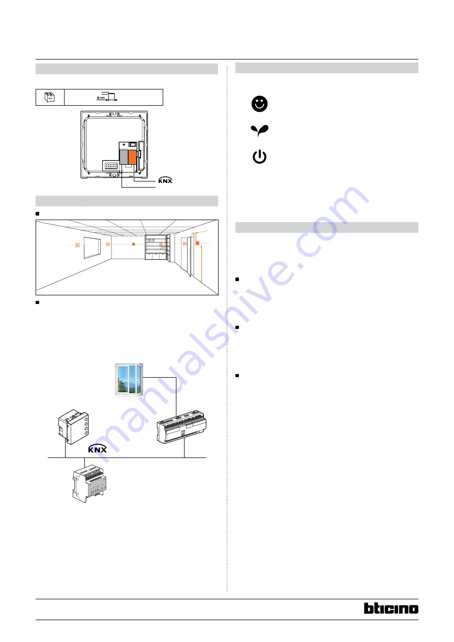
5. CONNECTION
KNX red/black connector
4 x (Ø 0.6mm <
< Ø 0.8mm)
29 V
=
6. INSTallaTION
6.1 Physical installation
150 cm
min. 20
6.2 System installation
This device has to be combined with a KNX room temperature controller
(with an embedded temperature control algorithm). Based on the
KNX BUS, the temperature control system can interact with other KNX
components as a guest room management system in a hotel and/or
building management system.
0 674 64
0 026 97
0 484 22
Test
230 V
50/60 Hz µ
μ
7. OPEraTINg MODES
The control panel can operate in the following modes:
Comfort: customisable setpoint: ideal heating and
cooling temperatures (default 21°C)
Eco: energy-saving heating and cooling temperatures
Frost protection: minimum safe temperature
Overheat protection: maximum safe temperature
With a short press (3 seconds maximum) of the MODE key, the system
toggles between comfort, frost and overheat protection. Eco mode can
also be set from the system.
8. SySTEM aPPlICaTIONS
The control panel can be set to manage three different applications,
depending on the type of system to be installed:
- Heating application (only heating is active)
- Cooling application (only cooling is active)
- Cooling and Heating application
8.1 heating application
If the measured temperature is lower than the reference value, the
heating system is activated and the corresponding symbol appears
on the display. When the temperature is reached, the control panel
switches the zone off and the icon disappears.
Note: The heating icon is always displayed.
8.2 Cooling application
If the measured temperature is higher than the reference value, the
cooling system is activated and the corresponding symbol appears
on the display. When the temperature is reached, the control panel
switches the zone off and the icon disappears.
Note: The cooling icon is always displayed.
8.3 heating and Cooling application
By configuring the control for both the heating and cooling functions,
it is possible to use it with the heating system in winter, and the cooling
system in summer. The icons shown on the display will be the same as
the ones previously described for the heating and cooling applications.
Depending on the measured temperature, the heating or cooling
system operating symbols (10 /11) will appear, to indicate that the
corresponding function is active.
If there are 2 tube fan coils, the changeover function can be used to
switch between the heating and cooling applications.
If there are 4 tube fan coils, the temperature control system can be
programmed for automatic operating mode. In this way, the (1/2) icons
are not displayed.


