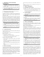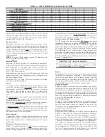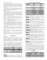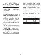
For specific duct types, follow instructions below:
A.
Round Metal Duct Work
1. Crimp end of branch duct.
2. Slip end of zone damper over end of duct work. Use
self-tapping sheet metal screw to secure. (See Fig. 2.)
3. Properly seal joint using duct tape, mastic, or other ap-
proved method. Do not allow mastic to come in contact
with actuator.
4. Insulate damper using 1-1/2 in. to 2-in. insulation. (Check
your local codes.)
NOTE:
All zone dampers and duct work must be properly
supported according to local codes or SMACNA standards.
B.
Rectangular Metal Duct Work
1. Make connections using S-lock and drives. (See Fig. 2.)
2. Properly seal joint using duct tape, mastic, or other ap-
proved method. Do not allow mastic to come in contact
with actuator.
3. Insulate damper using 1-1/2 in. to 2-in. insulation. (Check
your local codes.) (See Fig. 3.)
C.
Round Flexible Duct Work
1. Slip 1 end of flexible duct work over 1 end of zone damper.
(See Fig. 4.)
2. Secure flexible duct to zone damper using SMACNA or
other approved method.
3. Properly seal joint using duct tape, mastic, or other ap-
proved method. Do not allow mastic to come in contact
with actuator.
4. Insulate damper using 1-1/2 in. to 2-in. insulation. (Check
your local codes.) (See Fig. 5.)
NOTE:
All zone dampers and duct work must be properly
supported according to local codes or SMACNA standards.
D.
Rectangular Fibrous Glass Duct Work
1. Insert 1 end of zone damper into 1 end of fibrous glass duct
work approximately 2 to 3 in. (See Fig. 6.)
2. Screw field-supplied screws and tabs into zone damper.
3. Properly seal joint using duct tape, mastic, or other ap-
proved method. Do not allow mastic to come in contact
with actuator.
4. Insulate damper using 1-1/2 in. to 2-in. insulation. (Check
your local codes.) (See Fig. 7.)
V.
INSTALL BAROMETRIC BYPASS DAMPER
NOTE:
The barometric bypass damper is a critical part of Bryant
3-Zone System for controlling noise at minimum airflow. A
barometric bypass should be installed unless the duct work and
indoor unit have been sized for use without a bypass.
Fig. 1—Damper 24-vac Connections
C02083
OPN COM CLS
MOUNTING
HUB
ACTUATOR
HOUSING
MOUNTING
PLATE
FIELD
INSTALLED
POWER WIRING
QUICK BLADE
RELEASE
BUTTON (RED)
Fig. 2—Rectangular Metal Duct Work
A92478
DRIVE
ZONE
DAMPER
S-LOCK
SUPPLY
AIR DUCT
Fig. 3—Insulated Rectangular Metal Duct Work
A95131
1 / " TO 2"
INSULATION
1 2
Fig 4—Round Flexible Duct Work
A95132
FLEXIBLE
DUCT
ZONE
DAMPER
Fig. 5—Insulated Round Duct Work
A95133
/
″
STEEL STRAP
1 2
—3—
Содержание ZONEBB3Z
Страница 11: ...11...


