44
Step 14 — Check Belt Tension
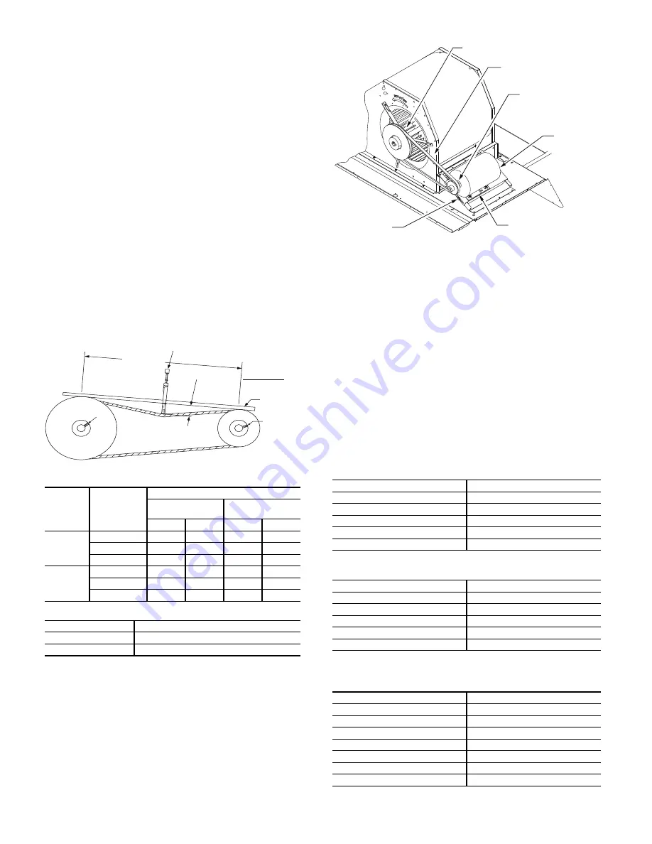
Measure the belt span length as shown in Fig. 57. Calculate the
required deflection by multiplying the belt span length by
1
/
64
.
For example, if the belt span length is 32 inches:
32 x
1
/
64
=
1
/
2
-in. deflection.
BELT FORCE — DEFLECTION METHOD
Check the belt tension with a spring-force belt force deflection
gage (available from drive belt manufacturer).
1. Place a straightedge along the belt between the two pul-
leys. Measure the distance between the motor shaft and the
blower shaft.
2. Set the tension gage to the desired tension (see Table 1 in
Fig. 57). Place the large O-ring at that point.
3. Press the tension checker downward on the belt until the
large O-ring is at the bottom of the straightedge.
4. Adjust the belt tension as needed.
Adjust belt tension by loosing the motor mounting plate front
bolts and rear bolt (see Fig. 58) and slide the plate towards the
fan (to reduce tension) or away from the fan (to increase ten-
sion). Ensure the blower shaft and motor shaft are parallel to
each other (pulleys aligned). Tighten all bolts securely when
finished.
BELT TENSION METHOD
Requires belt tension gage that measures tension in belt in units
of lbs force.
Fig. 57 — V-Belt Force Label
Fig. 58 — Belt Drive Motor Mounting
Pre-Start and Start-Up
This completes the mechanical installation of the unit. Refer to
the unit’s Service Manual for detailed Pre-Start and Start-Up
instructions. Download the latest versions from HVAC Part-
ners (www.hvacpartners.com).
Typical Unit Piping
Each heat pump refrigeration system includes a compressor, ac-
cumulator, reversing valve, dual-function outdoor coil with va-
por header check valve, cooling liquid line with a filter drier and
a check valve, dual-function indoor coil with a vapor header
check valve, and heating liquid line with a check valve and a
strainer. Unit sizes A04-06 have a single compressor-circuit. See
Fig. 59 and Tables 16-18 for typical unit piping schematic. Dual-
function outdoor and indoor coils are designed to provide paral-
lel coil circuits during evaporator-function operation and con-
verging coil circuits during the condenser-function operation.
TABLE 1
TABLE 2
BELT
CROSS
SECTION
SMALLEST
SHEAVE
DIAMETER
BELT DEFLECTION FORCE (LBS)
UNNOTCHED
BELTS
NOTCHED
BELTS
USED
NEW
USED
NEW
A, AX
3.0-3.6
3.7
5.5
4.1
6.1
3.8-4.8
4.5
6.8
5.0
7.4
5.0-7.0
5.4
8.0
5.7
8.4
B, BX
3.4-4.2
—
—
4.9
7.2
4.4-5.6
5.3
7.9
7.1
10.5
5.8-8.6
6.3
9.4
8.5
12.6
BELT CONDITION
TENSION FORCE IN BELT (LBS)
New
100
Used
80
TORQUE ALL SHEAVE SET SCREWS TO 110-130 in. lbs
SET
SCREW
SET
SCREW
STRAIGHT
EDGE
BELT SPAN
BELT DEFLECTION FORCE - SEE TABLE 1
DEFLECTION = BELT SPAN
64
Table 16 — Cooling Mode (each circuit)
COMPONENT
STATUS/POSITION
Reversing Valve
Energized
Check Valve A
Closed
Check Valve B
Open
Check Valve C
Closed
Check Valve D
Open
Table 17 — Heating Mode (each circuit)
COMPONENT
STATUS/POSITION
Reversing Valve
De-energized
Check Valve A
Open
Check Valve B
Closed
Check Valve C
Open
Check Valve D
Closed
Table 18 — Defrost Mode
A04-A06 Circuit 2
COMPONENT
STATUS/POSITION
Defrost Thermostat
Closed
Outdoor Fan(s)
Off
Reversing Valve
Energized
Check Valve A
Closed
Check Valve B
Open
Check Valve C
Closed
Check Valve D
Open
BLOWER PULLEY
V-BELT
MOTOR
PULLEY
MOTOR
MOTOR MOUNTING
PLATE
MOUNTING
BOLTS (4)
Содержание Preferred 549J 04
Страница 4: ...4 Fig 2 549J 04 06 Units Built On and After 4 15 2019...
Страница 5: ...5 Fig 3 549J 04 06 Units Built Prior to 4 15 2019...
Страница 6: ...6 Fig 4 549J 04 06 Corner Weights and Clearances...
Страница 7: ...7 Fig 5 549J 04 06 Base Rail Details...
Страница 8: ...8 Fig 6 549J 04 06 Thru the Base Charts...
Страница 23: ...23 Fig 41 Electro Mechanical Control Wiring 208 230v 460v...
Страница 24: ...24 Fig 42 Electro Mechanical Control Wiring 575v...
Страница 25: ...25 Fig 43 Electro Mechanical Power Wiring 208 230 1 60...
Страница 26: ...26 Fig 44 Electro Mechanical Power Wiring 208 230 3 60...
Страница 27: ...27 Fig 45 Electro Mechanical Power Wiring 460 3 60...
Страница 28: ...28 Fig 46 Electro Mechanical Power Wiring 575 3 60...
Страница 29: ...29 Fig 47 RTU Open System Control Wiring...


