b. Set up U-tube manometer or differential pressure gauge for measuring manifold pressure. (See Fig. 20).
c. Manometer or gauge must be able to read at least 0.0 to 3.0-in.w c of differential pressure, and resolve to at least 0.1-in. w c..
d. Turn boiler on.
e. Manifold pressure has been nominally set at 2.5-in. w.c. Manifold pressure and input rate must always be measured with pressure
regulator cover screw installed. Cover screw must be removed for adjustment. Manifold pressure reading will change (increase) when
cover screw is removed.
(1.) Remove regulator cover screw on top of gas valve, and insert an appropriate screwdriver into adjustment screw.
(2.) Turn adjustment screw clockwise to increase input rate, or counter clockwise to decrease input rate.
(3.) Replace cover screw, or cover hole temporarily with your finger to check new manifold pressure setting. Do not set manifold pressure
lower than 2.0-in. w.c. or higher than 3.0-in. w.c. when adjusting input rate.
(4.) Measure new input rate (cover screw must be installed). Repeat steps 1 through 4 until the input rate is within -/+ 2 percent of the
nameplate input rating.
(5.) If the actual input rate can not be set to within 2 percent of the correct input rating by adjusting manifold pressure, a change in gas
orifice size is required. Consult the boiler manufacturer for information on correct orifice sizing. The specific gravity (G) and the
higher heating value (HHV) of the local natural gas must be obtained from the local gas utility in order to determine the proper orifice
size.
(6.) After adjusting input rate, turn boiler off, remove manometer or pressure gauge, reinstall 1/8-in. plug on gas valve. Turn boiler on.
PROPANE GAS
1. This boiler must be converted for use with propane gas. A field-supplied, factory approved accessory conversion kit must be used. A factory
approved conversion kit is available from your local distributor.
2. Follow the instructions in the conversion kit.
3. Refer to Table 3 for the correct manifold pressure for the local altitude. The manifold pressure for propane gas ranges from 2.5-in.w.c. to
3.5-in.w.c. depending on the altitude.
WARNING: Operating this boiler with propane gas without a factory approved conversion kit may result in equipment
damage, fire, property damage, personal injury or death.
Restore all gas appliances that may have been shut off (while measuring boiler input rate) to normal operating conditions.
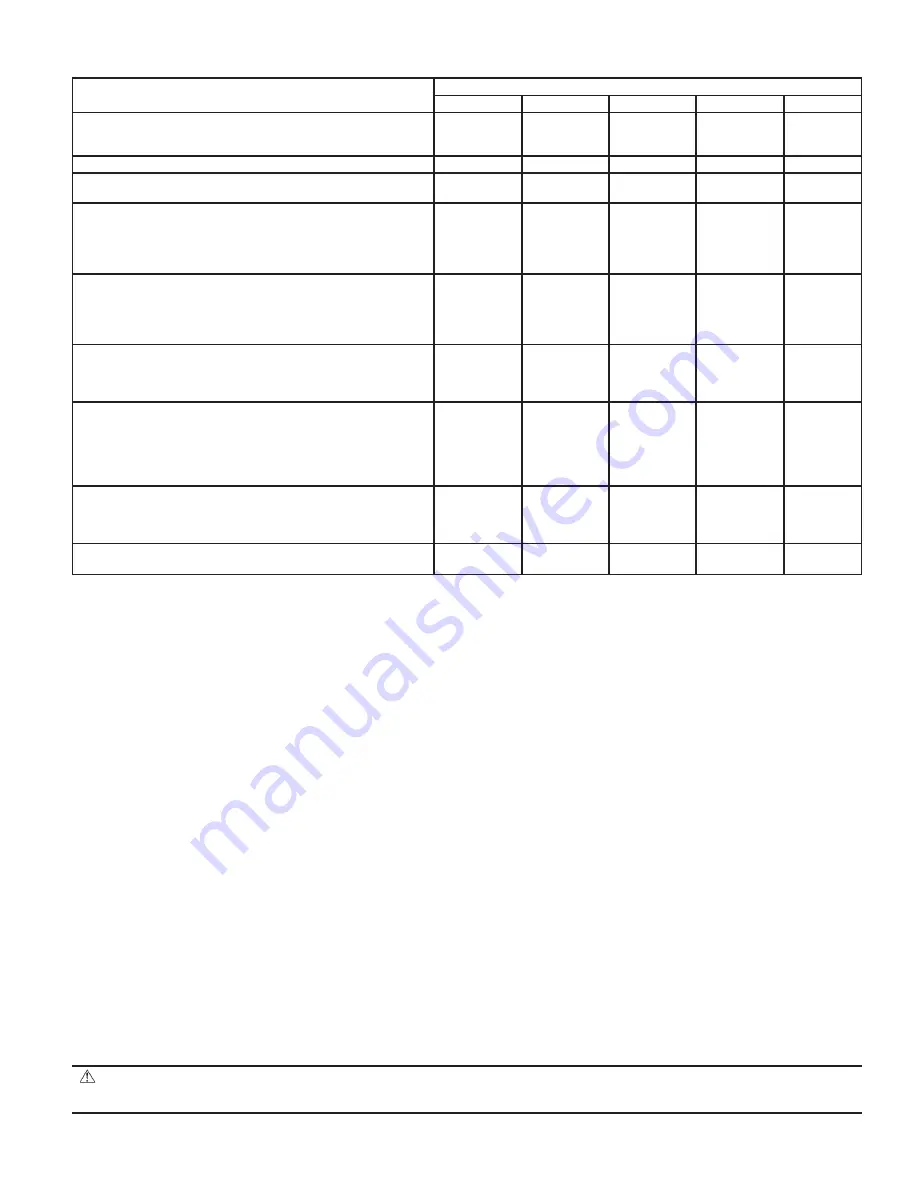
Table 9—Diagnostic Sequence
SEQUENCE OF OPERATION DIAGNOSTIC
DIAGNOSTIC INDICATOR LAMPS
A (Green)
B (Green)
C (Green)
D (Green)
E (Red)
Power ON, boiler standing by. Lamp A is illuminated indi-
cating 24 volt power is being supplied to the integrated boiler
control.
X
Thermostat calls for heat, energizing system circulator.
X
Integrated boiler control goes through self check of internal
circuitry (1-2 sec) and energizes draft inducer.
X
Draft inducer comes up to speed and establishes combustion
airflow, causing the normally open differential pressure air
proving switch contacts to close. Lamp B is illuminated indi-
cating that combustion air-flow is proved and the 15 sec pre
purge cycle is under way.
X
X
After pre purge, Lamp B goes out and Lamp C illuminates,
indicating the hot surface igniter is powered for the 20 sec
igniter warm-up period. The bright yellow orange glow of the
hot surface igniter can be observed through the observation
port in the front boiler section just above the igniter.
X
After igniter warm-up, the gas valve is energized, and opens
on the normal firing rate regulator (2.5-in. w.c.) for a 6 sec
trial for ignition. Lamp D illuminates. The blue orange glow
of the burner can be seen through the observation port.
X
X
X
X
2 sec later, Lamp C goes out as power is turned off to the
hot surface igniter. During the last two sec of the 6 sec trial
for ignition, main burner flame is proven by flame rectifica-
tion through the hot surface igniter, providing a flame signal
to the integrated boiler control. The gas valve remains ener-
gized, and the boiler runs.
X
X
X
Thermostat ends call for heat, de-energizing gas valve and
system circulator. Burner stops firing, and Lamp D goes out.
Draft inducer remains powered. Lamp B illuminates, indicat-
ing draft inducer is running for 30 sec postpurge.
X
X
After 30 sec, draft inducer is de-energized. Lamp B goes out.
Boiler stands by for next call for heat.
X
—27—
→
→
Содержание BW9
Страница 37: ...Fig 29 Troubleshooting Chart No 1 A00318 37 ...
Страница 39: ...Fig 31 Troubleshooting Chart No 3 A00319 39 ...
Страница 40: ...Fig 32 Troubleshooting Chart No 4 A00320 40 ...
Страница 41: ...Fig 33 Troubleshooting Chart No 5 A00321 41 ...
Страница 42: ...Fig 34 Troubleshooting Chart No 6 A00322 42 ...
Страница 46: ...Fig 38 Boiler Block and Piping Assembly A99176 46 ...
Страница 51: ... 51 ...
Страница 52: ... 2003 CAC BDP 7310 W Morris St Indianapolis IN 46231 imbw9a03 52 Catalog No 63BW 9A4 ...


