PROCEDURE 5—CHECK OUT PROCEDURE AND ADJUSTMENTS
A.
Verify Proper Sequence of Operation
The sequence can be followed via the diagnostic indicator lamps on the Integrated Boiler Control (IBC) in Fig. 21 and Table 9. This is the normal
sequence of operation. A more detailed sequence of operation containing potential faults can be found in the service hints section.
NOTE:
DO NOT use stop leak compounds. Leaks in threaded connections in the aluminum boiler sections must be repaired immediately.
Aluminum threads will not seal themselves.
B.
Inspect Venting and Air Intake System
Operate the boiler and verify that all vent/air intake connections are gastight and watertight. Repair any leaks immediately.
C.
Inspect Condensate Drain
Verify that all connections are watertight, and that condensate flows freely. Repair any leaks immediately.
D.
Inspect System Piping
Verify that all connections are watertight. Repair any leaks immediately.
E.
Test Ignition System Safety Shutoff Device
1. Turn off manual gas valve.
2. Set thermostat to call for heat.
3. Boiler begins normal sequence of operation.
4. After approximately 40 sec (pre-purge and igniter warm-up period), lamp D illuminates, indicating gas valve is powered.
5. After 6 sec, gas valve closes, lamp D goes out as integrated boiler control senses that flame is not present.
6. To restart system, follow operating instructions under
″
Start-up-Place in Operation
″
.
The following steps and diagram indicate the location of the connection points required to measure the manifold pressure.
The manifold pressure may be measured using a U-tube manometer or a differential pressure gauge (Magnehelic). The diagram shows the
connection of both measuring devices, but only one is required. (See Fig. 22.)
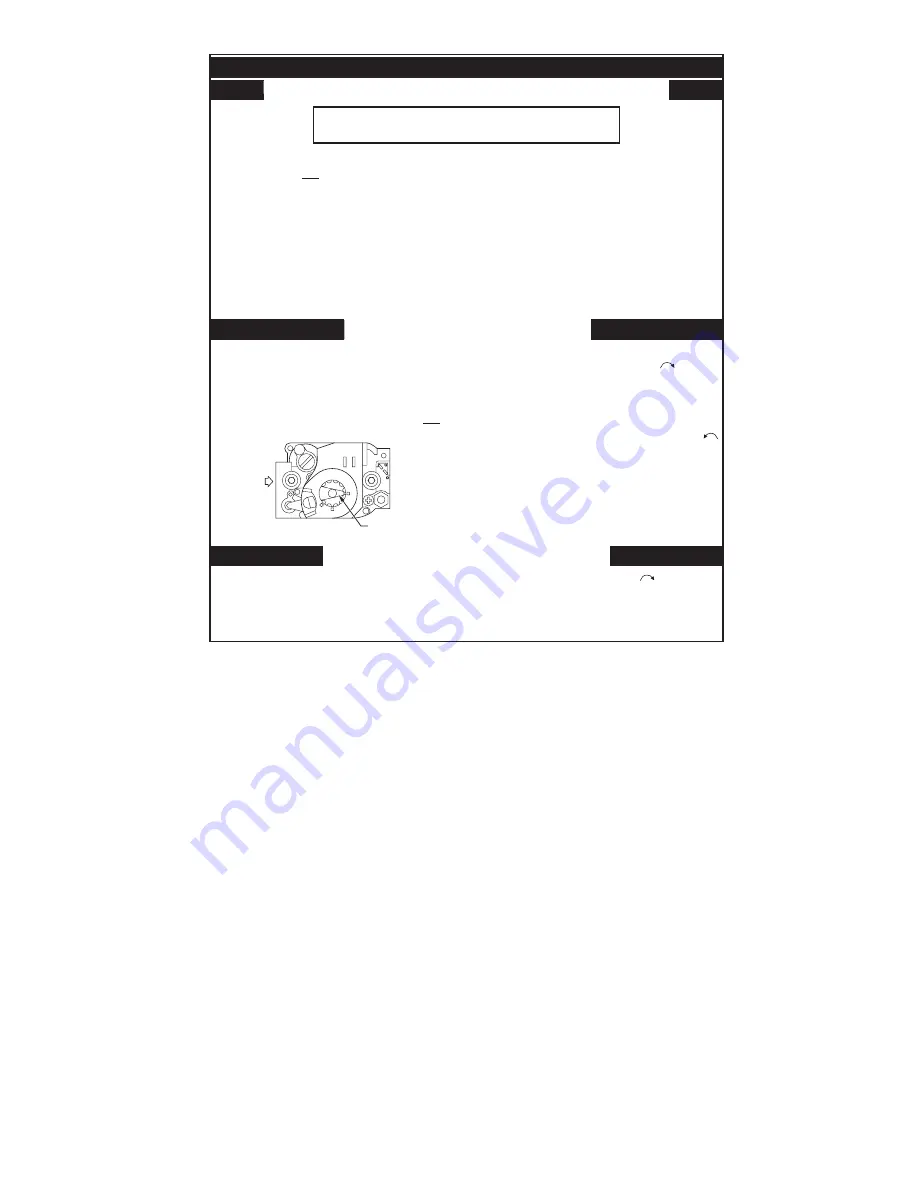
Fig. 20—Operating Label
A99169
WARNING: If you do not follow these instructions exactly, a fire
or explosion may result causing property damage, personal injury
or loss of life.
A. This appliance does not have a pilot. It is equipped
with an ignition device which automatically lights
the burner. Do not try to light the burner by hand.
B. BEFORE OPERATING smell all around the
appliance area for gas. Be sure to smell next to the
floor because some gas is heavier than air and will
settle on the floor.
WHAT TO DO IF YOU SMELL GAS
•
Do not try to light any appliance.
•
Do not touch any electric switch; do not use any
phone in your building.
•
Immediately call your gas supplier from a
neighbor’s phone. Follow the gas supplier’s
instructions.
FOR YOUR SAFETY READ BEFORE OPERATING
1. STOP! Read the safety information above on this
label.
2. Set the thermostat to lowest setting.
3. Turn off all electric power to the appliance.
4. This appliance is equipped with an ignition device
which automatically lights the burner. Do not try to
light the burner by hand.
1. Set the thermostat to lowest setting.
2. Turn off all electric power to the appliance if service
is to be performed.
3. Remove the front jacket panel.
OPERATING INSTRUCTIONS
TO TURN OFF GAS TO APPLIANCE
• If you cannot reach your gas supplier, call the
fire department.
C. Use only your hand to turn the gas control knob.
Never use tools. If the knob will not turn by hand,
don’t try to repair it, call a qualified service
technician. Force or attempted repair may result
in a fire or explosion.
D. Do not use this appliance if any part has been
under water. Immediately call a qualified service
technician to inspect the appliance and to replace
any part of the control system and any gas control
which has been under water.
5. Remove the front jacket panel.
6. Turn the gas control knob clockwise to "OFF".
7. Wait five (5) minutes to clear out any gas. Then
smell for gas, including near the floor. If you
smell gas, STOP! Follow "B" in the safety
information above on this label. If you don’t smell
gas, go to next step.
8. Turn the gas control knob counter clockwise
to "ON"
9. Replace the front jacket panel.
10. Turn on all electric power to the appliance.
11. Set thermostat to desired setting.
12. If the appliance will not operate. Follow the
instructions "To Turn Off Gas To Appliance" and
call your service technician or gas supplier.
4. Turn gas control knob clockwise to “OFF”.
Do not force.
5. Replace the front jacket panel.
GAS CONTROL
KNOB SHOWN
IN "ON" POSITION
GAS
INLET
OFF
ON
—25—
→
Содержание BW9
Страница 37: ...Fig 29 Troubleshooting Chart No 1 A00318 37 ...
Страница 39: ...Fig 31 Troubleshooting Chart No 3 A00319 39 ...
Страница 40: ...Fig 32 Troubleshooting Chart No 4 A00320 40 ...
Страница 41: ...Fig 33 Troubleshooting Chart No 5 A00321 41 ...
Страница 42: ...Fig 34 Troubleshooting Chart No 6 A00322 42 ...
Страница 46: ...Fig 38 Boiler Block and Piping Assembly A99176 46 ...
Страница 51: ... 51 ...
Страница 52: ... 2003 CAC BDP 7310 W Morris St Indianapolis IN 46231 imbw9a03 52 Catalog No 63BW 9A4 ...


