background image

7

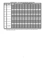
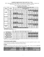
MAXIMUM EQUIVALENT VENT LENGTH -- FT. (M)

Table 3 – Maximum Equivalent Vent Length -- Ft. (M)

4501 to 10,000 Ft. (0 to 1370 M) Altitude

NOTE: Maximum Equivalent Vent Length (MEVL) does NOT include elbows or terminations. Use Table 2 - Deductions from

Maximum Equivalent Vent Length to determine allowable vent length for each application.

Altitude

FT (M)

Unit Size

DIRECT VENT (2-PIPE) AND NON---DIRECT VENT (1---PIPE)

Vent Pipe Diameter

1-1/2

2

2-1/2

3

4

4501 to 5000

(1370 to

1524)

40,000*

33

(10.1)

171

(52.1)

196

(59.7)

NA

NA

60,000

20

(6.1)

111

(33.8)

198

(60.4)

221

(67.4)

NA

80,000

13

(4.0)

54

(16.5)

146

(44.5)

195

(59.4)

216

(65.8)

100,000

NA

16

(4.9)

91

(27.7)

200

(61.0)

222

(67.7)

120,000

NA

NA

NA

80

(24.4)

211

(64.3)

5001 to 6000

(1524 to

1829)

40,000*

27

(8.2)

158

(48.2)

179

(54.6)

NA

NA

60,000

16

(4.9)

103

(31.4)

186

(56.7)

207

(63.1)

NA

80,000

11

(3.4)

49

(14.9)

137

(41.8)

183

(55.8)

200

(61.0)

100,000

NA

12

(3.7)

85

(25.9)

188

(57.3)

208

(63.4)

120,000

NA

NA

NA

74

(22.6)

199

(60.7)

6001 to 7000

(1829 to

2134)

40,000*

21

(6.4)

145

(44.2)

162

(49.4)

NA

NA

60,000

13

(4.0)

96

(29.3)

174

(53.0)

194

(59.1)

NA

80,000

NA

44

(13.4)

120

(36.6)

171

(52.1)

185

(56.4)

100,000

NA

10

(3.0)

79

(24.1)

178

(54.3)

195

(59.4)

120,000

NA

NA

NA

68

(20.7)

187

(57.0)

7001 to 8000

(2134 to

2438)

40,000*

15

(4.6)

133

(40.5)

146

(44.5)

NA

NA

60,000

10

(3.0)

89

(27.1)

163

(49.7)

181

(55.2)

NA

80,000

NA

40

(12.2)

120

(36.6)

159

(48.5)

170

(51.8)

100,000

NA

NA

73

(22.3)

167

(50.9)

182

(55.5)

120,000

NA

NA

NA

62

(18.9)

175

(53.3)

8001 to 9000

(2438 to

2743)

40,000*

10

(3.0)

121

(36.9)

130

(39.6)

NA

NA

60,000

7

(2.1)

82

(25.0)

152

(46.3)

168

(51.2)

NA

80,000

NA

35

(10.7)

111

(33.8)

148

(45.1)

156

(47.5)

100,000

NA

NA

67

(20.4)

157

(47.9)

170

(51.8)

120,000

NA

NA

NA

56

(17.1)

164

(50.0)

9001 to

10,000

(2743 to

3048)

40,000*

5

(1.5)

110

(33.5)

115

(35.1)

NA

NA

60,000

NA

76

(23.2)

142

(43.3)

156

(47.5)

NA

80,000

NA

31

(9.4)

103

(31.4)

137

(41.8)

142

(43.3)

100,000

NA

NA

62

(18.9)

147

(44.8)

157

(47.9)

120,000

NA

NA

NA

51

(15.5)

153

(46.6)

*Not all families have these models.

Notes:

1. 3--- and 4---in. Vent pipe systems require long radius elbows.
2. Total equivalent vent lengths under 10’ for 40,000 require the use of an outlet choke plate at altitude 0 to 2,000 ft (0 to 610M).

Failure to use an outlet choke when required may result in flame disturbance or flame sense lockout.

3. Vent sizing for Canadian installations over 4500 ft (1370m) above sea level are subject to acceptance by the local authorities having jurisdiction.
4. NA --- Not allowed; pressure switch will not close, or flame disturbance may result.
5. Do not use pipe size greater than those specified in table or incomplete combustion, flame disturbance, or flame sense lockout may occur.
6. Size both the combustion---air and vent pipe independently, then use the larger diameter for both pipes.
7. Assume the two 45

_

elbows equal one 90

_

elbow. Wide radius elbows are desirable and may be required in some cases.

8. Elbows and pipe sections within the furnace casing and at the vent termination should not be included in vent length or elbow count.
9. The minimum pipe length is 5 ft. (1.5 M) for all applications.

10. Use 3---in. (76 mm) diameter vent termination kit for installations requiring 4---in. (102 mm) diameter pipe.

Содержание 925TA

Страница 1: ...em S Fan On Plus technology allows control of continuous fan speed from a compatible thermostat S External Media Filter Cabinet included S 4 way multipoise design for upflow downflow or horizontal ins...

Страница 2: ...ry Supplied Media Cabinet Field Supplied Filter Filter Used for Certified Watt Data KGAWF1606UFR KGAWF1306UFR KGAWF1406UFR KGAWF1506UFR KGAWF1506UFR Electrical Data 030040 042060 048080 048100 066120...

Страница 3: ...66 2200 CFM 0 5 ESP 040 40 000 BTU 060 60 000 BTU 080 80 000 BTU 100 100 000 BTU 120 120 000 BTU Not all familes have these models A11164 FURNACE COMPONENTS RATING PLATE NOT SHOWN LOCATED ON BLOWER DO...

Страница 4: ...as Orifice Kit 1 30mm LP KGAHA5750130 X X X X X Indoor Air Quality Bryant Perfect Air Purifier 16x25 406x635 mm GAPAAXBB1625 A08 X X X X X Bryant Perfect Air Purifier 20x25 508x635 mm GAPAAXBB2025 A08...

Страница 5: ...0 1050 2 Org 1180 1130 1095 1060 1015 975 935 895 850 800 1 Red 1100 1045 1010 970 920 885 845 790 745 690 100000 SIDE BOTTOM 5 Gry 2040 1970 1885 1795 1720 1635 1540 1450 1360 1230 4 Yel 1550 1505 14...

Страница 6: ...202 61 6 224 68 3 100 000 NA 17 5 2 94 28 7 205 62 5 229 69 8 120 000 NA NA NA 83 25 3 217 66 1 Not all families have these models NOTE See notes at end of venting tables NOTE See Table 3 for altitude...

Страница 7: ...0 39 6 NA NA 60 000 7 2 1 82 25 0 152 46 3 168 51 2 NA 80 000 NA 35 10 7 111 33 8 148 45 1 156 47 5 100 000 NA NA 67 20 4 157 47 9 170 51 8 120 000 NA NA NA 56 17 1 164 50 0 9001 to 10 000 2743 to 304...

Страница 8: ...0 125 0 20 0 70 0 175 0 177 0 147 0 M 6 1 19 5 19 5 17 1 14 3 6 1 21 3 52 7 45 7 38 1 6 1 21 3 53 3 53 9 44 8 0 20 Ft 20 0 32 0 30 0 22 0 11 0 20 0 70 0 104 0 87 0 67 0 20 0 70 0 124 0 104 0 82 0 M 6...

Страница 9: ...heat exchangers motors and controls 60 80 27 C 16 C SUPPLY AIR A10490 MINIMUM CLEARANCES TO COMBUSTIBLE MATERIALS POSITION CLEARANCE Rear 0 0 mm Front Combustion air openings in furnace and in struct...

Страница 10: ...ed Coil Assembly or Coil Box 22 1 8 562 0 19 482 6 23 3 4 603 3 20 3 8 517 5 1 The plenum should be constructed 1 4 in 6 mm smaller in width and depth than the plenum dimensions shown above Concentric...

Страница 11: ...ELD SUPPLIED FUSED DISCONNECT JUNCTION BOX 24 VOLT TERMINAL BLOCK THREE WIRE HEATING ONLY FIVE WIRE NOTE 2 NOTE 1 1 STAGE THERMOSTAT TERMINALS FIELD SUPPLIED FUSED DISCONNECT CONDENSING UNIT FURNACE C...

Страница 12: ...B OUTLET WIDTH A 22 558 3 14 13 16 376 3 35 889 0 5 8 15 8 1 5 16 33 3 29 1 2 749 3 19 1 8 485 8 VENT AIR INTAKE AIR FLOW AIR FLOW SIDE INLET SIDE INLET CONDENSATE DRAIN TRAP LOCATION THERMOSTAT ENTRY...

Страница 13: ...___ Media Filter Casing Casing shall be of 030 in thickness minimum pre painted galvanized steel Draft Inducer Motor Draft inducer motor shall be two speed design Primary Heat Exchangers Primary heat...

Страница 14: ...change at any time specifications or designs without notice and without incurring obligations E2011 Bryant Heating Cooling Systems D 7310 W Morris St D Indianapolis IN 46231 Printed in U S A Edition D...

Отзывы: