45
(cooling second stage - Y2 is energized), then the control will
bring on compressor stage 1 to maintain the mixed air tempera-
ture setpoint. The EconoMi$er IV and X damper will be open
at maximum position.
Heating
The sequence of operation for the heating is the same as an
electromechanical unit with no economizer. The only differ-
ence is how the economizer acts. The economizer will stay at
the Economizer Minimum Position while the evaporator fan is
operating. The outdoor air damper is closed when the indoor
fan is not operating.
Optional Perfect Humidity™ dehumidification system
Units with the factory-equipped Perfect Humidity option are
capable of providing multiple modes of improved dehumidifi-
cation as a variation of the normal cooling cycle. The Perfect
Humidity option includes additional valves in the liquid line
and discharge line of each refrigerant circuit, a small reheat
condenser coil downstream of the evaporator, and Motormas-
ter
®
variable-speed control of some or all outdoor fans. Opera-
tion of the revised refrigerant circuit for each mode is described
below.
The Perfect Humidity system provides three sub-modes of
operation: Cool, Reheat1, and Reheat2.
Cool mode
Provides a normal ratio of sensible and latent cooling effect
from the evaporator coil.
Reheat1
Provides increased latent cooling while slightly reducing the
sensible cooling effect.
Reheat2
Provides normal latent cooling but with null or minimum sensi-
ble cooling effect delivered to the space.
The Reheat1 and Reheat2 modes are available when the unit is
not in a heating mode and when the low ambient lockout switch
is closed.
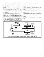
The following diagrams depict piping for single stage cooling
units.
NORMAL COOLING MODE - PERFECT HUMIDITY SYSTEM WITH SINGLE STAGE COOLING
CONDEN
S
ER COIL
PERFECT HUMIDITY COIL
EVAPORATOR COIL
COMPRE
SS
OR
OUTDOOR AIR
INDOOR LEAVING
AIR
INDOOR ENTERING
AIR
D
S
Vx
VALVE
C
S
Vx
VALVE
ACUTROL
METERING
DEVICE
REHEAT MODE
METERING
DEVICE (TXV)
= CLO
S
ED VALVE
= OPEN VALVE


