background image

2

C06108

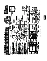
Fig. 1

---

Horizontal Conversion Panels

Step 1

Provide Unit Support

Roof Curb

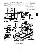
Assemble and install accessory roof curb in accordance with
instructions shipped with curb. (See Fig. 2.) Install insulation,

cant strips, roofing felt, and counter flashing as shown.

Ductwork

must be attached to curb, not to the unit.

If electric control power

or gas service is to be routed through the basepan, attach the

accessory thru-the-bottom service connections to the basepan in
accordance with

the accessory

installation instructions.

Connections must be installed before unit is set on roof curb.

IMPORTANT

: The gasketing of the unit to the roof curb is

critical for a watertight seal. Install gasket supplied with the roof
curb as shown in Fig. 2. Improperly applied gasket can result in
air leaks and poor unit performance.
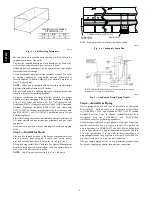
Curb should be level. Unit leveling tolerances are shown in Fig.
3. This is necessary for unit drain to function properly. Refer to

Accessory Roof Curb Installation Instructions for additional

information as required.

Slab Mount (Horizontal Units Only)

Provide a level concrete slab that extends a minimum of 6 in.
beyond unit cabinet. Install a gravel apron in front of

condenser-coil air inlet to prevent grass and foliage from
obstructing airflow.

NOTE

: Horizontal units may be installed on a roof curb if

required.

Alternate Unit Support

When the curb or adapter cannot be used, support unit with

sleeper rails using unit curb or adapter support area. If sleeper
rails cannot be used, support the long sides of the unit with a

minimum of 3 equally spaced 4-in. x 4-in. pads on each side.

Step 2

Field Fabricate Ductwork

Secure all ducts to roof curb and building structure on vertical

discharge units.

Do not connect ductwork to unit.

For horizontal

applications, field-supplied isolation flanges should be attached to
horizontal discharge openings and all ductwork should be secured

to the flanges. Insulate and weatherproof all external ductwork,
joints, and roof openings with counter flashing and mastic in

accordance with applicable codes.
Ducts passing through an unconditioned space must be insulated

and covered with a vapor barrier.
If a plenum return is used on a vertical unit, the return should be
ducted through the roof deck to comply with applicable fire

codes.

A minimum clearance is not required around ductwork. Cabinet
return-air static pressure (a negative condition) shall not exceed

0.35 in. wg with economizer or 0.45 in. wg without economizer.
These units are designed for a minimum continuous return-air

temperature in heating of 50

_

F (dry bulb), or an intermittent

operation down to 45

_

F (dry bulb), such as when used with a

night setback thermostat.
To operate at lower return-air temperatures, a field-supplied
outdoor air temperature control must be used to initiate both

stages of heat when the temperature is below 45

_

F. Indoor

comfort may be compromised when these lower air temperatures
are used with insufficient heating temperature rise.

Step 3

Install External Trap for Condensate

Drain

The unit’s

3

/

4

-in. condensate drain connections are located on the

bottom and side of the unit. Unit discharge connections do not

determine the use of drain connections; either drain connection

can be used with vertical or horizontal applications.
When using the standard side drain connection, ensure the plug

(Red) in the alternate bottom connection is tight before installing
the unit.
To use the bottom drain connection for a roof curb installation,

relocate the factory-installed plug (Red) from the bottom
connection to the side connection. The center drain plug looks

like a star connection, however it can be removed with a

1

/

2

-in.

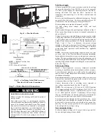
socket drive extension. (See Fig. 4.) The piping for the

condensate drain and external trap can be completed after the unit
is in place.
All units must have an external trap for condensate drainage.

Install a trap 4-in. deep and protect against freeze-up. If drain line
is installed downstream from the external trap, pitch the line away

from the unit at 1 in. per 10 ft of run. Do not use a pipe size
smaller than the unit connection (

3

/

4

in.). (See Fig. 5.)

Step 4

Rig and Place Unit

Inspect unit for transportation damage, and file any claim with

transportation agency. Keep unit upright and do not drop.
Spreader bars are not required if top crating is left on unit, and

rollers may be used to move unit across a roof. Level by using
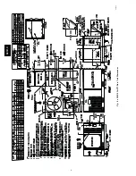
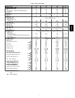
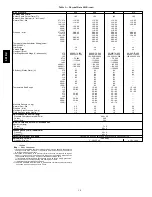
unit frame as a reference. See Table 1 and 2 and Fig. 6 for

additional information. Operating weight is shown in Table 1 and

2 and Fig. 6.
Lifting holes are provided in base rails as shown in Fig. 8 and 9.

Refer to rigging instructions on unit.

PROPERTY DAMAGE HAZARD

Failure to follow this warning could result in personal

injury, death and property damage.
All panels must be in place when rigging and lifting.

!

WARNING

Positioning

Maintain clearance around and above unit to provide minimum

distance from combustible materials, proper airflow, and service

access. (See Fig. 7, 8 and 9.)
Position unit on roof curb so that the following clearances are

maintained:

1

/

4

in. clearance between the roof curb and the base

rail inside the front and rear, 0.0 in. clearance between the roof

curb and the base rail inside on the duct end of the unit. This will

result in the distance between the roof curb and the base rail
inside on the condenser end of the unit being approximately

equal to Fig. 2, section C-C.
Do not install unit in an indoor location. Do not locate unit air

inlets near exhaust vents or other sources of contaminated air.

581B

,C

Содержание 581B036--072

Страница 1: ...all brazing operations Recognize safety information This is the safety alert symbol When you see this symbol on the unit and in instructions or manuals be alert to the potential for personal injury Understand the signal words DANGER WARNING and CAUTION These words are used with the safety alert symbol DANGER identifies the most serious hazards which will result in severe personal injury or death W...

Страница 2: ...ght setback thermostat To operate at lower return air temperatures a field supplied outdoor air temperature control must be used to initiate both stages of heat when the temperature is below 45_F Indoor comfort may be compromised when these lower air temperatures are used with insufficient heating temperature rise Step 3 Install External Trap for Condensate Drain The unit s 3 4 in condensate drain...

Страница 3: ...ide 7 Direction of airflow 8 Connector packages CRBTMPWR001A01 and 002A01 are for thru the curb type gas Packages CRBTMPWR003A01 and 004A01 are for thru the bottom type gas connections CONNECTOR PKG ACCY B C D ALT DRAIN HOLE GAS POWER CONTROL ACCESSORY POWER CRBTMPWR001A01 1 911 16 551 1 4 406 13 4 44 5 3 4 19 NPT 3 4 19 NPT 1 2 12 7 1 2 12 7 CRBTMPWR002A01 11 4 31 7 CRBTMPWR003A01 1 2 12 7 NPT 3 ...

Страница 4: ... rigging skids Step 5 Install Flue Hood Flue hood is shipped screwed to the burner compartment access panel Remove from shipping location and using screws provided install flue hood in location shown in Fig 8 and 9 For units being installed in California Air Quality Management Districts which require NOx emissions of 40 nanograms joule or less a low NOx unit must be installed NOTE Low NOx units ar...

Страница 5: ...73 69 1872 35 50 902 33 31 847 072 635 288 73 69 1872 35 50 902 41 31 1050 C06208 Fig 7 Roof Curb Alignment Support gas piping as shown in the table in Fig 11 For example a 3 4 in gas pipe must have one field fabricated support beam every 8 ft Therefore an 18 ft long gas pipe would have a minimum of 3 support beams and a 48 ft long pipe would have a minimum of 6 support beams PROPERTY DAMAGE HAZAR...

Страница 6: ...6 CONTROL BOX COMPRESSOR ACCESS PANEL C06363 Fig 8 581B 036 072 Base Unit Dimensions 581B C ...

Страница 7: ...7 COMPRESSOR ACCESS PANEL C06364 Fig 9 581C 024 060 Base Unit Dimensions 581B C ...

Страница 8: ...phases must be balanced within 2 and the current within 10 Use the formula shown in Tables 3 and 4 Note 3 to determine the percent voltage imbalance Operation on improper line voltage or excessive phase imbalance constitutes abuse and may cause damage to electrical components Such operation would invalidate any applicable Bryant warranty NOTE If accessory thru the bottom connections and roof curb ...

Страница 9: ... 1 10 x 10 1 10 x 10 1 10 x 10 Nominal Cfm 1200 1600 2000 2400 Maximum Continuous Bhp Std 1 20 1 20 1 30 2 40 2 40 Hi Static 2 40 2 40 2 90 2 90 Motor RPM Std 1620 1620 1725 1725 Hi Static 1725 1725 1725 1725 Motor Frame Size Std 48 48 48 56 56 Hi Static 56 56 56 56 Fan Rpm Range Std 680 1044 770 1185 1035 1460 1119 1585 Hi Static 1075 1455 1075 1455 1300 1685 1300 1685 Motor Bearing Type Ball Bal...

Страница 10: ...0 80 50 80 071 15 45 15 45 15 45 114 55 85 35 65 35 65 149 50 80 50 80 060N 20 50 20 50 20 50 090N 30 60 30 60 30 60 120N 40 70 40 70 Manifold Pressure in wg Natural Gas Std 3 5 3 5 3 5 3 5 Propane Alt 3 5 3 5 3 5 3 5 Maximum Static Pressure in wg 1 0 1 0 1 0 1 0 Field Gas Connection Size in 1 2 1 2 1 2 1 2 HIGH PRESSURE SWITCH psig Standard Compressor Internal Relief 450 50 Cutout 428 Reset Auto ...

Страница 11: ...N Centrifugal Type Belt Drive Quantity Size in 1 10 x 10 1 10 x 10 1 10 x 10 1 10 x 10 Nominal Cfm 800 1200 1600 2000 Maximum Continuous Bhp Std 0 58 1 20 1 20 1 30 2 40 Hi Static 2 40 2 40 2 90 Motor Frame Size Std 48 48 48 48 56 Hi Static 56 56 56 Motor Rpm 1620 1620 1620 1725 Fan Rpm Range Std 400 1000 680 1044 770 1185 1035 1460 Hi Static 1075 1455 1075 1455 1300 1685 Motor Bearing Type Ball B...

Страница 12: ...0 80 50 80 071 15 45 15 45 15 45 114 55 85 35 65 35 65 149 50 80 50 80 060N 20 50 20 50 20 50 090N 30 60 30 60 30 60 120N 40 70 40 70 Manifold Pressure in wg Natural Gas Std 3 5 3 5 3 5 3 5 Propane Alt 3 5 3 5 3 5 3 5 Maximum Static Pressure in wg 1 0 1 0 1 0 1 0 Field Gas Connection Size in 1 2 1 2 1 2 1 2 HIGH PRESSURE SWITCH psig Standard Compressor Internal Relief 450 50 Cutout 428 Reset Auto ...

Страница 13: ...60 11 13 23 21 C TO TB2 BLK YEL BLU FIELD POWER SUPPLY DISCONNECT PER NEC 575 3 60 SIZES 581B060 072 C06346 Fig 12 Power Wiring Connections WIRE CONNECTIONS TO LOW VOLTAGE SECTION COOL STAGE 1 FAN HEAT STAGE 1 COOL STAGE 2 HEAT STAGE 2 24 VAC HOT 24 VAC COM N A OUTDOOR AIR SENSOR Y1 W2 G W W1 Y Y2 O W2 R C S1 S2 THERMOSTAT DIPSWITCH SETTINGS R G Y1 Y2 W1 W2 C IPD X ON OFF A B C D LEGEND NOTE Under...

Страница 14: ...0 1 145 STD 2 2 NO 11 9 15 11 6 53 048 460 3 60 STD 414 508 1 7 1 45 1 0 8 0 3 2 2 YES 14 6 20 14 1 55 048 4 tons 460 3 60 HS 414 508 1 7 1 45 1 0 8 0 3 2 6 NO 12 3 15 12 1 67 4 tons HS 2 6 YES 15 0 20 14 6 70 STD 1 9 NO 10 1 15 9 9 44 STD 1 0 6 1 9 YES 12 3 15 11 9 46 575 3 60 HS 518 632 1 6 1 38 1 0 6 0 3 2 0 NO 10 2 15 10 0 51 575 3 60 HS 518 632 1 6 1 38 0 3 2 0 YES 12 4 15 12 0 52 Perfect 1 0...

Страница 15: ...ES 13 7 15 13 70 STD 1 9 NO 10 3 15 10 45 STD 1 0 4 0 3 1 9 YES 12 5 15 12 47 575 3 60 HS 518 632 1 6 4 40 1 0 4 0 3 2 0 NO 10 4 15 10 52 575 3 60 HS 518 632 1 6 4 40 2 0 YES 12 6 15 12 53 Perfect 1 0 4 0 9 2 6 NO 11 0 15 11 61 Perfect Humidity 1 0 4 0 9 2 6 YES 13 2 15 13 63 208 230 1 60 STD 187 254 1 28 8 169 1 1 5 0 6 6 6 NO 44 1 60 42 206 208 230 1 60 STD 187 254 1 28 8 169 1 1 5 0 6 6 6 YES 5...

Страница 16: ... Mizer circuit recommended relay HN61KK324 See Fig 18 The relay coil is connected between the DEHUM output and C common of the unit The relay controls thePerfect Humidity solenoid valve and must be wired between the Perfect Humidity fuse and the low pressure switch Refer to the installation instructions included with the Bryant Light Commercial Thermidistat device for more information Manual Outdo...

Страница 17: ...Unit Shown ROOF TOP UNIT R C Y1 Y2 G W1 W2 PINK PINK RED 24V FROM PERFECT HUMIDITY SYSTEM LLSV R1 TS TAT WIRES LCT R C Y1 Y2 G W1 W2 DEHUM OC R1 PERFECT HUMIDITY SYSTEM PINK LTLO CB 3 2 AMPS LEGEND CB Circuit Breaker LCT Light Commercial Thermidistat Device LLSV Liquid Line Solenoid Valve LTLO Low Temperature Lockout C06360 Fig 18 Typical Rooftop Unit with Perfect Humidity Adaptive Dehumidificatio...

Страница 18: ...ssembly 3 The indoor coil access panel will be used as the top of the hood Remove the screws along the sides and bottom of the indoor coil access panel See Fig 26 4 Swing out indoor coil access panel and insert the hood sides under the panel hood top Use the screws provided to attach the hood sides to the hood top Use screws provided to attach the hood sides to the unit See Fig 27 5 Remove the shi...

Страница 19: ...ure sensor is a 3k ohm thermistor located at the inlet of the indoor fan See Fig 34 This sensor is factory installed The operating range of temperature measurement is 0 to 158_F See Table 5 for sensor temperature resistance values Table 5 Supply Air Sensor Temperature Resistance Values TEMPERATURE F RESISTANCE ohms 58 200 250 40 100 680 22 53 010 4 29 091 14 16 590 32 9 795 50 5 970 68 3 747 77 3 ...

Страница 20: ...that contains both 33ZCSENCO2 and 33ZCASPCO2 accessories Differential Dry Bulb Control For differential dry bulb control the standard outdoor dry bulb sensor is used in conjunction with an additional accessory dry bulb sensor part number CRTEMPSN002A00 The accessory sensor must be mounted in the return airstream See Fig 37 Wiring is provided in the EconoMi er IV wiring harness See Fig 29 In this m...

Страница 21: ...of the transformer grounded 3 For field installed remote minimum position POT remove black wire jumper between P and P1 and set control minimum position POT to the minimum position 8 7 C06028 Fig 29 EconoMi er IV Wiring 0 500 1000 1500 2000 2500 0 05 0 15 0 25 STATIC PRESSURE in wg FLOW IN CUBIC FEET PER MINUTE cfm C06030 Fig 30 Barometric Flow Capacity 0 5 10 15 20 25 30 0 13 0 20 0 22 0 25 0 30 ...

Страница 22: ...volatile organic compound ventilation requirements The maximum demand ventilation position is used for fully occupied ventilation When demand ventilation control is not being used the minimum position potentiometer should be used to set the occupied ventilation position The maximum demand ventilation position should be turned fully clockwise Adjust the minimum position potentiometer to allow the m...

Страница 23: ...uired per person using normal outside air design criteria Demand Controlled Ventilation DCV When using the EconoMi er IV for demand controlled ventilation there are some equipment selection criteria which should be considered When selecting the heat capacity and cool capacity of the equipment the maximum ventilation rate must be evaluated for design conditions The maximum damper position must be c...

Страница 24: ... of the CO2 sensor For example a 1100 ppm set point relates to a 15 cfm per person design Use the 1100 ppm curve on Fig 40 to find the point when the CO2 sensor output will be 6 7 volts Line up the point on the graph with the left side of the chart to determine that the range configuration for the CO2 sensor should be 1800 ppm The EconoMi er IV controller will output the 6 7 volts from the CO2 sen...

Страница 25: ... recovery unit and or a dehumidification option should be considered Step 9 Adjust Evaporator Fan Speed Adjust evaporator fan speed to meet jobsite conditions Tables 8 and 9 show fan rpm at motor pulley settings Tables 10 and 14 show maximum amp draw of belt drive motor Table 13 shows sound data Refer to Tables 15 34 for performance data See Table 11 for accessory static pressure drop See Fig 41 f...

Страница 26: ...mA 0 1100 1100 50 5 Economizer Proportional 20 0 10V 4 20 mA 0 900 900 50 6 Economizer Exponential 15 0 10V 4 20 mA 0 1100 1100 50 7 Exponential 20 0 10V 4 20 mA 0 900 900 50 8 Health Safety Proportional 0 10V 4 20 mA 0 9999 5000 500 9 Parking Air Intakes Loading Docks Proportional 0 10V 4 20 mA 0 2000 700 50 LEGEND ppm Parts Per Million 6000 5000 4000 3000 2000 1000 0 0 0 05 0 1 0 15 0 2 0 25 0 3...

Страница 27: ... 30 1455 208 230 7 0 060 208 230 6 7 060 Three 2 40 2120 460 3 0 Three 2 40 2120 575 3 0 208 230 6 7 072 Three 2 40 2120 460 3 0 072 Three 2 40 2120 575 3 0 LEGEND Bhp Brake Horsepower Extensive motor and electrical testing on these units ensures that the full horsepower and watts range of the motors can be utilized with confidence Using the fan motors up to the ratings shown in this table will no...

Страница 28: ...testing on these units ensures that the full range of the motor can be utilized with confidence Using the fan motors up to the ratings shown will not result in nuisance tripping or premature motor failure Unit warranty will not be affected See Tables 8 and 9 for additional information 3 Use of a field supplied motor may affect wire sizing Contact your Bryant representative to verify 4 Interpolatio...

Страница 29: ...er rpms require field supplied drive Table 17 Fan Performance 581B 036 581C 036 Vertical Discharge Units High Static Motor Belt Drive AIRFLOW EXTERNAL STATIC PRESSURE in wg AIRFLOW CFM 0 2 0 4 0 6 0 8 1 0 CFM Rpm Bhp Watts Rpm Bhp Watts Rpm Bhp Watts Rpm Bhp Watts Rpm Bhp Watts 900 567 0 15 145 688 0 22 222 786 0 30 296 871 0 37 368 947 0 44 437 1000 599 0 18 177 717 0 27 265 814 0 35 349 897 0 43...

Страница 30: ... 73 730 1027 0 89 888 1101 1 05 1040 1170 1 20 1189 1800 885 0 66 652 978 0 83 826 1060 1 00 994 1133 1 16 1157 1900 923 0 75 745 1014 0 94 930 1093 1 11 1109 2000 962 0 85 847 1049 1 05 1043 AIRFLOW EXTERNAL STATIC PRESSURE in wg AIRFLOW CFM 1 2 1 4 1 6 1 8 2 0 CFM Rpm Bhp Watts Rpm Bhp Watts Rpm Bhp Watts Rpm Bhp Watts Rpm Bhp Watts 1200 1093 0 77 767 1155 0 87 861 1213 0 96 955 1268 1 05 1047 1...

Страница 31: ...1 1 64 1627 1376 1 79 1779 1428 1 94 1930 1479 2 09 2078 1900 1293 1 63 1620 1350 1 79 1784 1405 1 96 1946 1457 2 12 2106 1506 2 28 2265 2000 1323 1 79 1776 1380 1 96 1950 1434 2 13 2123 1486 2 31 2293 NOTES 1 Grey cells indicate field supplied drive is required 2 Maximum continuous bhp is 2 40 3 See general fan performance notes LEGEND Bhp Brake Horsepower Watts Input Watts to Motor Motor drive r...

Страница 32: ...Fan Performance 581B 060 581C 060 Vertical Discharge Units High Static Motor Belt Drive AIRFLOW EXTERNAL STATIC PRESSURE in wg AIRFLOW CFM 0 2 0 4 0 6 0 8 1 0 CFM Rpm Bhp Watts Rpm Bhp Watts Rpm Bhp Watts Rpm Bhp Watts Rpm Bhp Watts 1500 848 0 42 371 968 0 55 486 1069 0 68 600 1158 0 80 715 1238 0 94 831 1600 887 0 49 433 1004 0 63 556 1103 0 76 678 1190 0 90 800 1269 1 04 922 1700 927 0 57 502 10...

Страница 33: ...3 1429 1 96 1736 1503 2 19 1945 2600 1305 1 63 1448 1390 1 89 1677 1468 2 14 1900 1540 2 38 2117 2700 1348 1 80 1602 1431 2 07 1841 1507 2 33 2073 2800 1392 1 99 1768 1472 2 27 2016 2900 1435 2 19 1945 3000 1479 2 40 2135 AIRFLOW EXTERNAL STATIC PRESSURE in wg AIRFLOW CFM 1 2 1 4 1 6 1 8 2 0 CFM Rpm Bhp Watts Rpm Bhp Watts Rpm Bhp Watts Rpm Bhp Watts Rpm Bhp Watts 1800 1406 1 43 1273 1475 1 58 140...

Страница 34: ...2 0 CFM Rpm Bhp Watts Rpm Bhp Watts Rpm Bhp Watts Rpm Bhp Watts Rpm Bhp Watts 1800 1406 1 43 1273 1475 1 58 1403 1540 1 72 1531 1601 1 87 1657 1660 2 00 1780 1900 1438 1 58 1401 1505 1 73 1541 1569 1 89 1678 1630 2 04 1813 1689 2 19 1945 2000 1470 1 73 1537 1537 1 90 1686 1600 2 06 1833 1660 2 23 1977 1718 2 38 2118 2100 1502 1 89 1681 1568 2 07 1840 1631 2 25 1996 1690 2 42 2149 1747 2 59 2300 22...

Страница 35: ... Fan Performance 581B 036 581C 036 Horizontal Discharge Units High Static Motor Belt Drive AIRFLOW EXTERNAL STATIC PRESSURE in wg AIRFLOW CFM 0 2 0 4 0 6 0 8 1 0 CFM Rpm Bhp Watts Rpm Bhp Watts Rpm Bhp Watts Rpm Bhp Watts Rpm Bhp Watts 900 553 0 14 134 681 0 22 221 782 0 32 316 870 0 42 417 948 0 53 526 1000 582 0 16 163 707 0 26 257 807 0 36 358 894 0 47 466 971 0 58 580 1100 612 0 20 196 734 0 3...

Страница 36: ... Watts Rpm Bhp Watts Rpm Bhp Watts Rpm Bhp Watts 1200 643 0 23 234 762 0 34 343 859 0 46 458 944 0 58 579 1020 0 71 705 1300 675 0 28 277 790 0 40 394 886 0 52 517 969 0 65 644 1044 0 78 777 1400 707 0 33 326 819 0 45 452 913 0 58 581 996 0 72 716 1070 0 86 855 1500 740 0 38 382 849 0 52 515 941 0 66 653 1023 0 80 795 1096 0 95 941 1600 773 0 45 444 879 0 59 586 970 0 73 731 1050 0 88 880 1123 1 0...

Страница 37: ...9 0 98 867 1206 1 11 986 1279 1 25 1111 2000 1001 0 84 744 1085 0 96 855 1163 1 09 972 1238 1 23 1095 2100 1043 0 96 850 1123 1 09 965 1199 1 22 1086 2200 1085 1 09 966 1162 1 22 1086 2300 1127 1 23 1092 2400 2500 AIRFLOW EXTERNAL STATIC PRESSURE in wg AIRFLOW CFM 1 2 1 4 1 6 1 8 2 0 CFM Rpm Bhp Watts Rpm Bhp Watts Rpm Bhp Watts Rpm Bhp Watts Rpm Bhp Watts 1500 1247 0 98 873 1320 1 13 1002 1390 1 ...

Страница 38: ...All other rpms require field supplied drive Table 32 Fan Performance 581B 060 581C 060 Horizontal Discharge Units High Static Motor Belt Drive AIRFLOW EXTERNAL STATIC PRESSURE in wg AIRFLOW CFM 0 2 0 4 0 6 0 8 1 0 CFM Rpm Bhp Watts Rpm Bhp Watts Rpm Bhp Watts Rpm Bhp Watts Rpm Bhp Watts 1500 800 0 39 350 904 0 49 438 999 0 60 535 1087 0 72 640 1169 0 85 753 1600 839 0 46 412 938 0 57 505 1030 0 68...

Страница 39: ...3 2 24 1990 2500 1196 1 51 1345 1273 1 73 1538 1345 1 96 1738 1412 2 19 1945 2600 1238 1 69 1497 1312 1 91 1697 1382 2 14 1904 1448 2 38 2117 2700 1280 1 87 1660 1352 2 10 1867 1420 2 34 2081 2800 1322 2 07 1835 1392 2 31 2050 2900 1364 2 28 2023 3000 AIRFLOW EXTERNAL STATIC PRESSURE in wg AIRFLOW CFM 1 2 1 4 1 6 1 8 2 0 CFM Rpm Bhp Watts Rpm Bhp Watts Rpm Bhp Watts Rpm Bhp Watts Rpm Bhp Watts 180...

Страница 40: ...80 1 87 1660 1352 2 10 1867 1420 2 34 2081 1484 2 59 2300 1546 2 84 2526 2800 1322 2 07 1835 1392 2 31 2050 1458 2 56 2270 1521 2 81 2496 2900 1364 2 28 2023 1432 2 53 2245 1496 2 78 2472 3000 1406 2 50 2224 1472 2 76 2452 AIRFLOW EXTERNAL STATIC PRESSURE in wg AIRFLOW CFM 1 2 1 4 1 6 1 8 2 0 CFM Rpm Bhp Watts Rpm Bhp Watts Rpm Bhp Watts Rpm Bhp Watts Rpm Bhp Watts 1800 1322 1 56 1382 1388 1 77 15...

Страница 41: ...during shipping and handling carefully straighten fins with a fin comb 4 Verify the following conditions a Make sure that condenser fan blade are correctly positioned in fan orifice See Condenser Fan Adjustment section for more details b Make sure that air filter s is in place c Make sure that condensate drain trap is filled with water to ensure proper drainage d Make sure that all tools and misce...

Страница 42: ...rs are factory set and should require no adjustment TO CHECK ignition of main burners and heating controls move thermostat set point above room temperature and verify that the burners light and evaporator fan is energized Check heating effect then lower the thermostat setting below the room temperature and verify that the burners and evaporator fan turn off Refer to Tables 35 and 36 for the correc...

Страница 43: ...en thermostat calls for cooling terminals G and Y1 are energized The indoor fan contactor IFC reversing valve solenoid RVS and compressor contactor are energized and indoor fan motor compressor and outdoor fan starts The outdoor fan motor runs continuously while unit is cooling Heating Units Without Economizer When the thermostat calls for heating terminal W1 is energized To prevent thermostat sho...

Страница 44: ...perature increases the latent capacity of the rooftop unit The refrigerant passes through the evaporator and is turned into a vapor The air passing over the evaporator coil will become colder than during normal operation However as this same air passes over the subcooling coil it will be slightly warmed partially reheating the air Subcooling mode operates only when the outside air temperature is w...

Страница 45: ...rning could cause personal injury or death When sevicing unit shut off all electrical power to unit and install lockout tag WARNING Step 1 Cleaning Inspect unit interior at the beginning of heating and cooling season and as operating conditions require Evaporator Coil 1 Turn unit power off tag disconnect Remove evaporator coil access panel 2 If economizer or two position damper is installed remove...

Страница 46: ...n A 024 060 and 072 208 230 v 072 460 v 2 75 3 50 C06138 Fig 50 Condenser Fan Adjustment Step 4 EconoMi er IV Adjustment Refer to Optional EconoMi er IV section Step 5 Evaporator Fan Belt Inspection Check condition of evaporator belt or tension during heating and cooling inspections or as conditions require Replace belt or adjust as necessary Step 6 High Pressure Switch The high pressure switch co...

Страница 47: ... be within the normal operating range of the unit Perfect Humidity System Charging The system charge for units with the Perfect Humidity adaptive dehumidification system is greater than that of the standard unit alone The charge for units with this option is indicated on the unit nameplate drawing Also refer to Fig 55 58 To charge systems using the Perfect Humidity adaptive dehumidification system...

Страница 48: ...e solenoid valve MUST be energized to use the charging charts and the outdoor motor speed controller jumpered to run the fan at full speed The charts reference a liquid pressure psig and temperature at a point between the condenser coil and the subcooling reheat dehumidification coil A tap is provided on the unit to measure liquid pressure entering the subcooling reheat dehumidification coil IMPOR...

Страница 49: ... To Use Cooling Charging Charts Units With Perfect Humidityt Adaptive Dehumidification System Refer to charts Fig 55 58 to determine the proper leaving condenser pressure and temperature Example Fig 55 Leaving Condenser Pressure 250 psig Leaving Condenser Temperature 105 F NOTE When using the charging charts it is important that only the subcooling reheat dehumidification coil liquid line solenoid...

Страница 50: ...Line Pressure kpa F C 125 52 115 46 105 41 95 35 85 29 75 24 C06148 Fig 59 Cooling Charging Chart Standard 581C 024 581C 3 TON CHARGING CHART 65 0 75 0 85 0 95 0 43 48 53 58 63 68 73 78 Suction Line Temp deg F Suction Line Pressure psig 448 2 498 2 548 2 598 2 648 2 6 1 11 1 16 1 21 1 Suction Line Temperature deg C Suction Line Pressure kpa F C 115 46 105 41 95 35 85 29 75 24 C06149 Fig 60 Cooling...

Страница 51: ...15 46 105 41 95 35 85 29 75 24 C06150 Fig 61 Cooling Charging Chart Standard 581C 048 581C 5 TON CHARGING CHART 55 0 65 0 75 0 85 0 95 0 105 0 115 0 42 47 52 57 62 67 72 77 Suction Line Temp deg F Suction Line Pressure psig 310 0 410 0 510 0 610 0 710 0 810 0 0 0 5 0 10 0 15 0 20 0 25 0 Suction Line Temperature deg C Suction Line Pressure kpa F C 115 46 105 41 95 35 85 29 75 24 C06151 Fig 62 Cooli...

Страница 52: ... least 5 seconds Table 38 LED Error Code Description LED INDICATION ERROR CODE DESCRIPTION ON Normal Operation OFF Hardware Failure 1 Flash Evaporator Fan On Off Delay Modified 2 Flashes Limit Switch Fault 3 Flashes Flame Sense Fault 4 Flashes 4 Consecutive Limit Switch Faults 5 Flashes Ignition Lockout Fault 6 Flashes Induced Draft Motor Fault 7 Flashes Rollout Switch Fault 8 Flashes Internal Con...

Страница 53: ...ve burner rack from unit as described above 2 Inspect burners and if dirty remove burners from rack 3 Using a soft brush clean burners and cross over port as required 4 Adjust spark gap See Fig 65 5 Reinstall burner rack as described above Step 15 Replacement Parts A complete list of replacement parts may be obtained from any Bryant distributor upon request Refer to Fig 66 for a typical unit wirin...

Страница 54: ...ntegrated Gas Unit Controller LPS Low Pressure Switch LS Limit Switch MGV Main Gas Valve Splice Splice Marked Factory Wiring Field Control Wiring Field Power Wiring Accessory or Optional Wiring To indicate common potential only not to represent wiring NOTES 1 If any of the original wire furnished must be replaced it must be replaced with type 90 C wire or its equivalent 2 Three phase motors are pr...

Страница 55: ...er completing troubleshooting DCV Demand Controlled Ventilation and Power Exhaust To check DCV and Power Exhaust 1 Make sure EconoMi er IV preparation procedure has been performed 2 Ensure terminals AQ and AQ1 are open The LED for both DCV and Exhaust should be off The actuator should be fully closed 3 Connect a 9 v battery to AQ positive node and AQ1 negative node The LED for both DCV and Exhaust...

Страница 56: ...ame that should not be present Reset unit If problem persists replace control board 4 Consecutive Limit Switch Faults LED 4 Flashes Inadequate airflow to unit Check operation of indoor evaporator fan motor and that supply air temperature rise agrees with range on unit nameplate information Ignition Lockout LED 5 Flashes Unit unsuccessfully attempted ignition for 15 minutes Check ignitor and flame ...

Страница 57: ...g mode for a one minute minimum Wait until mandatory one minute time period has elapsed or reset power to unit Table 41 Perfect Humidity Adaptive Dehumidification System Subcooling Mode Service Analysis PROBLEM CAUSE REMEDY Subcooling Mode Liquid Reheat Will Not Energize No power to control transformer from evaporator fan motor Check power source and evaporator fan relay Ensure all wire connection...

Страница 58: ...refrigerant system Locate restriction and remove Compressor Operates Continuously Dirty air filter Replace filter Compressor Operates Continuously Unit undersized for load Decrease load or increase unit size Thermostat set too low Reset thermostat Low refrigerant charge Locate leak repair and recharge Leaking valves in compressor Replace compressor Air in system Recover refrigerant evacuate system...

Страница 59: ... Modulating between l d d DCV Above set DCV LED On High Free Cooling LED Off Low On Off On Off Modulating between min position and DCV maximum Modulating between closed and DCV maximum Off Off Off Off maximum Low F C li LED O High On On On Off Modulating Modulating Low Free Cooling LED On High On Off Off Off Modulating Modulating Off Off Off Off For single enthalpy control the module compares outd...

Страница 60: ...j CHECK PULLEY ALIGNMENT AND BELT TENSION PER INSTALLATION INSTRUCTIONS III START UP ELECTRICAL SUPPLY VOLTAGE L1 L2 L2 L3 L3 L1 COMPRESSOR AMPS L1 L2 L3 INDOOR FAN AMPS L1 L2 L3 TEMPERATURES OUTDOOR AIR TEMPERATURE DB RETURN AIR TEMPERATURE DB WB COOLING SUPPLY AIR DB HEATING SUPPLY AIR DB PRESSURES Cooling Mode GAS INLET PRESSURE IN WG GAS MANIFOLD PRESSURE IN WG HIGH FIRE REFRIGERANT SUCTION PS...

Отзывы: