PRE-START-UP
Crankcase heaters are energized as long as there is power to
the unit. Energize heaters 24 hours prior to unit start-up.
Proceed as follows to inspect and prepare the unit for initial
startup:
1. Remove all access panels.
2. Read and follow instructions on all WARNING, CAU-
TION, and INFORMATION labels attached to, or shipped
with, unit.
3. Make the following inspections:
a. Inspect for shipping and handling damages such as
broken lines, loose parts, disconnected wires, etc.
b. Inspect for oil at all refrigerant tubing connections
and on unit base. Detecting oil generally indicates a
refrigerant leak. Leak-test all refrigerant tubing con-
nections using electronic leak detector, halide torch,
or liquid-soap solution. If refrigerant leak is de-
tected, see Refrigerant Leaks section on page 26.
c. Inspect all field- and factory-wiring connections. Be
sure that connections are completed and tight.
WARNING:
Failure to observe the following warn-
ings could result in serious personal injury:
1. Follow recognized safety practices and wear pro-
tective goggles when checking or servicing refrig-
erant system.
2. Do not operate compressor or provide any electric
power to unit unless compressor terminal cover is
in place and secured.
3. Do not remove compressor terminal cover until all
electrical sources have been disconnected.
4. Relieve all pressure from system before touching
or disturbing anything inside terminal box if re-
frigerant leak is suspected around compressor
terminals.
5. Never attempt to repair soldered connection while
refrigerant system is under pressure.
6. Do not use torch to remove any component. Sys-
tem contains oil and refrigerant under pressure.
To remove a component, wear protective goggles
and proceed as follows:
a. Shut off electrical power to unit.
b. Relieve all pressure from system.
c. Cut component-connecting tubing with tubing
cutter and remove component from unit.
d. Carefully unsweat remaining tubing stubs when
necessary. Oil can ignite when exposed to torch
flame.
d. Inspect coil fins. If damaged during shipping and
handling, carefully straighten fins with a fin comb.
4. Verify the following conditions:
a. Make sure that outdoor-fan blade is correctly posi-
tioned in fan orifice. Blades should clear fan motor
and fan orifice ring.
b. Make sure that air filters are in place.
c. Make sure that condensate drain pan and trap are
filled with water to ensure proper drainage.
d. Make sure that all tools and miscellaneous loose parts
have been removed.
5. Compressors are internally spring mounted. Do not loosen
or remove compressor holddown bolts.
6. Each unit system has 3 Schrader-type ports: one on the
suction line, one on the liquid line, and one on the com-
pressor discharge line. Be sure that caps on the ports
are tight.
Unit is now ready for initial start-up.
START-UP
I. HEATING SECTION START-UP AND ADJUSTMENTS
CAUTION:
Complete the required procedures given
in the Pre-Start-Up section on this page before starting
unit.
Do not jumper any safety devices when operating the unit.
A. Checking Heating Control Operation
Start and check the unit for proper heating control operation
as follows:
1. Turn on unit electrical supply.
2. Set System switch selector at HEAT position and Fan
switch at AUTO. or ON position. Set heating tempera-
ture lever above room temperature.
3. The indoor fan will start immediately.
4. Check diffusers for heating operation.
Adjust airflow to be between 142 and 236 L/s (300 and 500
cfm) per 3.5 kW (12,000 Btuh) cooling.
To shut off unit, set system selector switch at OFF position
or set heating selector lever below room temperature.
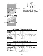
B. Heating Sequence of Operation (See Fig. 31)
Upon a request for heating from the space thermostat, ter-
minal W1 will be energized with 24 v. On units with econo-
mizer, the economizer damper blade will move to minimum
position regardless of the outdoor-air temperature, and the
unit will operate as described in Cooling, Without Accessory
Economizer section on page 20. The IFC, OFC, C1 and C2
will be energized. The reversing valves switch position and
the indoor fan, outdoor fan, Compressor no. 1, and Compres-
sor no. 2 are energized.
If the space temperature continues to fall while W1 is ener-
gized, W2 will be energized with 24 v, and the heater contac-
tor(s) (HC) will be energized, which will energize the electric
heater(s).
When the space thermostat is satisfied, W2 will be deener-
gized first, and the electric heater(s) will be deenergized.
Upon a further rise in space temperature, W1 will be deen-
ergized, and the reversing valve solenoids (RVS1 and RVS2)
will be energized. On units with economizer, the economizer
damper blade will move to the fully closed position.
C. Defrost Cycle
When the temperature of the outdoor coil drops below -2 C
(28 F) as sensed by the defrost thermostat (DFT2) and the
defrost timer is at the end of a timed period (adjustable at
30, 50 or 90 minutes), RVS1 and RVS2 are energized and the
OFC is deenergized. This switches the position of the revers-
ing valves and shuts off the outdoor fan. The electric heaters
(if installed) will be energized. On units with economizer, the
economizer damper blade will move to the fully closed
position.
The unit continues to defrost until the coil temperature as
measured by DFT2 reaches 18 C (65 F) or the duration of de-
frost cycle completes a 10-minute period.
During the defrost mode, if circuit 1 defrosts first, RVS1 will
oscillate between heating and cooling modes until the defrost
mode is complete.
At the end of the defrost cycle, the electric heaters (if in-
stalled) will be deenergized; the reversing valves switch and
—18—
Содержание 548C Series
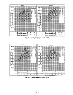
Страница 27: ...Fig 38 Cooling Charging Charts 548C090 Fig 39 Cooling Charging Charts 548C120 27 ...
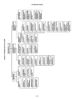
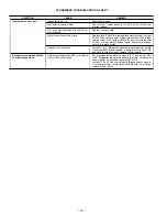
Страница 28: ...TROUBLESHOOTING HEATING TROUBLESHOOTING CHART 28 ...
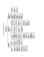
Страница 29: ...COOLING TROUBLESHOOTING CHART 29 ...
Страница 31: ......
Страница 32: ...Copyright 1992 Carrier Corporation CATALOG NO 000 376 ...


