


9. The chimney must extend 3 ft above highest point where it
passes through the roof of a building and at least 2 ft higher
than any portion of a building within a horizontal distance
of 10 ft. It shall also be extended at least 5 ft above highest
connected equipment flue collar.
10. Check local codes for any variance.
FACTORY-BUILT CHIMNEYS
Listed factory-built chimneys may be used. Refer to chimney
manufacturer’s instructions for proper installation.
E.
Oil Burner
This furnace is supplied with a high-pressure atomizing retention
head-type burner (for use with grade 1 or 2 fuel oil). The Riello oil
burner operates with a prepurge period of 10 seconds and a safety
timing of 5 seconds. The burner flange is factory installed for an
inspection length of 3 3/4–in. The oil pump is set to operate on a
single line system. To operate on a two-line system the by-pass
plug must be installed.
F.
Oil Connections
WARNING:
This burner is shipped with the oil pump
set to operate on a single line system. To operate on a
two-line system the by-pass plug must be installed. Do
not operate a single line system with the by-pass plug
installed. Operating a single line system with the by-pass
plug installed will result in damage to the pump shaft
seal..
Pump pressure must be set at time of burner start-up. A
pressure gauge is attached to the PRESSURE PORT for
pressure readings. Two PIPE CONNECTORS are sup-
plied with the burner for connection to either a single or
two-line system. Also supplied are two ADAPTORS,
two female 1/4–in. NPT, to adapt oil lines to burner pipe
connectors. All pump ports are British Parallel Thread
design. Direct connection of NPT threads to the pump
will damage the pump body.
Riello manometers and vacuum gauges do not require
any adapters and can be safely connected to the pump
ports. An NPT (metric) adapter must be used when
connecting other guage models.
Complete instructions for installing fuel oil piping can be found in
oil burner Installation Instructions included with furnace.
Oil line entry holes are provided in side panels. Two holes are
provided in each location so that a 2-pipe system may be used if
desired.
An oil filter should be used with all oil burners and should be
installed as close to burner as possible.
G.
Barometric Draft Control
The barometric draft control shipped with furnace MUST be used
with furnace to ensure proper operation. Instructions for installing
control are packed with control.
H.
Electrical Connections
WARNING:
The unit cabinet must have an uninter-
rupted or unbroken electrical ground to minimize per-
sonal injury if an electrical fault should occur. A green
ground screw is provided in control box for this connec-
tion.
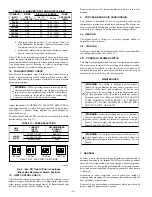
115-V WIRING
Before proceeding with electrical connections, make certain that
voltage, frequency, and phase correspond to that specified on unit
rating plate. Also, check to be sure that service provided by utility
is sufficient to handle load imposed by this equipment. Refer to
rating plate or Table 7 for equipment electrical specifications.
Make all electrical connections in accordance with National
Electrical Code (NEC) ANSI/NFPA 70-1996 and any local codes
or ordinances that might apply. For Canadian installations, all
electrical connections must be made in accordance with Canadian
Electrical Code CSA C22.1 or subauthorities having jurisdiction.
CAUTION:
Do not connect aluminum wire between
disconnect switch and furnace. Use only copper wire.
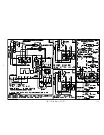
The control system depends on correct polarity of power supply.
Connect HOT wire (H) and NEUTRAL wire (N) as shown in Fig.
3 or Fig. 4.
A separate line voltage supply MUST be used with a fused
disconnect switch or circuit breaker between main power panel
and unit. (See Fig. 3 or Fig. 4.)
Metallic conduit (where required/used) may terminate at side panel
of unit. It is not necessary to extend conduit inside unit from side
panel to control box.
When replacing any original furnace wiring, use only 105°C No.
14 AWG copper wire.
24-V WIRING
Instructions for wiring thermostat (field supplied) are packed in
thermostat box. Make thermostat connections as shown in Fig. 3 or
Fig. 4 at 24-v terminal board on fan timer board.
ACCESSORIES
When installing optional accessories to this appliance, follow
manufacturer’s Installation Instructions included with accessory.
Other than wiring for thermostat, wire with a minimum of type
″
T
″
insulation (63°F rise) must be used for accessories.
I.
Horizontal or Downflow Installation
For horizontal installation, determine which
″
side
″
will become the
″
top
″
, when the unit is laid down. Remove the flue pipe clearance
knock-out from the top of that side panel. Install the flue elbow so
that it exits the cabinet of the furnace through that opening.
For counterflow installation, the flue pipe must exit the cabinet
through 1 of the side panel openings (as above), then extended up
the side of the furnace. Insure that adequate clearances to com-
bustibles are observed. Downflow Conversion/Vent Guard Kit
MUST be used.
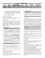
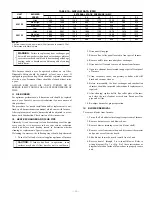
TABLE 7—ELECTRICAL DATA
UNIT
SIZE
VOLTS—
HERTZ—
PHASE—
OPERATING
VOLTAGE RANGE
MAX
UNIT
AMPS
MIN
WIRE
GAGE
MAX WIRE
LENGTH (FT)†
MAX FUSE OR
CKT BKR AMPS‡
Max*
Min*
036105
115—60—1
132
104
12.2
14
26
15
060120
115—60—1
132
104
15.7
14
26
20
—6—
Содержание 369RAN
Страница 8: ...Fig 3 Wiring Diagram 036105 A00420 8...
Страница 9: ...Fig 4 Wiring Diagram 060120 A00419 9...


