


Understand the signal words DANGER, WARNING, and CAU-
TION. These words are used with the safety-alert symbol. DAN-
GER identifies the most serious hazards which will result in severe
personal injury or death. WARNING signifies a hazard which
could result in personal injury or death. CAUTION is used to
identify unsafe practices which would result in minor personal
injury or product and property damage.
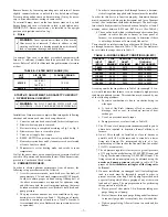
INTRODUCTION
The model 369RAN Furnaces are available in 2 sizes. Each size
unit is capable of 3 heat/airflow combinations by a simple nozzle
change. Unit 036105 covers inputs of 70,000, 91,000, and 105,000
Btuh, and unit 060120 covers inputs of 119,000, 140,000 and
154,000 Btuh. This eliminates the need to stock 6 separate units
This furnace is a multipoise unit. It may be installed in the upflow,
downflow or horizontal configuration.
The furnace is shipped as a packaged unit, complete with burner
and controls. It requires a line voltage (115 vac) connection to
control box, a thermostat hook-up as shown on wiring diagram, oil
line connection(s), adequate duct work, and connection to a
properly sized vent.
The air handling capacity of this furnace is designed for cooling
airflow. Refer to Table 12 for expected airflows at various external
duct static pressures.
LOCATION
I.
GENERAL
WARNING:
This furnace is not water tight and is not
designed for outdoor installation. This furnace shall be
installed in such a manner as to protect electrical com-
ponents from water. Outdoor installation would lead to a
hazardous electrical condition and to premature furnace
failure.
WARNING:
Do not use this furnace as a construction
heater. Use of this furnace as a construction heater
exposes furnace to abnormal conditions, contaminated
combustion air, and lack of air filters. Failure to follow
this warning can lead to premature furnace failure and/or
vent failure which could result in a fire hazard and/or
bodily harm.
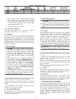
Fig. 2—Dimensional Drawing
DIMENSIONS (IN.)
UNIT SIZE
A
B
C
D
E
F
G
H
J
K
L
036105
35
48-3/4
30-1/4
16-5/8
20
22
12
14
5
1-1/2
1-3/4
060120
39-1/2
53
32-1/4
18-3/4
24
28
12-9/32
16
6
1-5/8
1-1/2
A98037
3
″
19
″
20
″
20
″
19
″
2
″
PULL
OIL INLET
(BOTH SIDES)
VENT CONN
ELECTRICAL
CONNECTIONS
(BOTH SIDES)
.88 DIAM TYP
KNOCK-OUT BOTH SIDES
FOR J DIAM VENT
TOP KNOCK-OUT
FOR J DIAM VENT
A
E
G
B
L
H
C
D
F
K
—2—
Содержание 369RAN
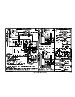
Страница 8: ...Fig 3 Wiring Diagram 036105 A00420 8...
Страница 9: ...Fig 4 Wiring Diagram 060120 A00419 9...


