Installation and Maintenance Instructions
JSE1-0129MAEAD Extruder Clutch
1. INSTALLATION
a. Coupling should be installed with pins/buffers removed.
b. Apply an anti-seize compound to the gearbox input shaft.
c. Slide gearbox coupling half (1-23) onto gearbox shaft.
d. Slide motor hub onto shaft.
e. If interference or press fit is specified, heat coupling hub per fit
specified before putting hub onto shaft.
f. Bolt Rigid Hub (1-16) to the Module Carrier Plate (1-19). Using qty.
8, M16 x 65 S.H.C.S. (1-2). Torque tighten to 130 lb ft.
g. Dial indicate coupling Misalignment tolerance: Angular .004”,
Radial .003”. If misalignment is beyond tolerance, realign.
h. Assemble bolts and Buffers with Buffer Bush (1-10) inside of
Buffer (1-9) and a M16 Washer (1-11) on each side of the buffer.
Re-install 14 capscrews (1-12) with loctite on threads. Torque
tighten to 130 lbs.
2. TORQUE ADJUSTMENT & INITIAL STARTUP
a. These torque limiters were preset at the factory, no further
adjustment is required at this time.
b. If it is desired to adjust the release torque at a later date, refer to
#5 “Torque Adjustment”.
3. RESETTING
On overload, the Safety Element Ball is displaced and the Module
Carrier Plate disengages from the Detent Pocket Plate. With the
drive at rest (the power off) and the overload cleared, align the two
reset arrows (or grooves) on the Detent Pocket Plate and Module
Carrier Plate by turning the drive motor shaft by hand. After aligning
the match marks strike the safety element plunger shroud with a soft
mallet and the plunger will move back into the safety element 1/4
inch signifying that the unit is engaged.
DISCONNECTING
To manually disconnect the module, turn the disconnecting nut
(2-21) counter clockwise with a wrench until rotation stops. Modules
are now disconnected and torque limiter is free for checking motor
rotation or for greasing bearing and modules. To re-engage module,
turn disconnecting nut (2-21) clockwise until flush with housing nut
(2-7), then strike plunger shroud (2- 12) with a dead blow mallet.
4. GENERAL MAINTENACE
a. Grease 2-3 pumps from a grease gun into Grease Fitting (2-13)
every 3 months. Recommended grease is “Mobil XTC” - (Modules
Only).
b. Safety elements should be disassembled, inspected and
reassembled at least once every 3 years, more frequently where
frequent tripping occurs.
c. Bearings should be re-greased with Mobil SHC220 every 3
months. Add grease with a grease gun into fitting (1-7) and old
grease is purged from grease relief valve (1-18). Recommended
Bearing Grease:
Mobil SHC220
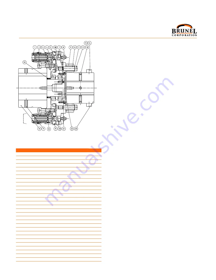
Figure 1
Section view of
Part # JSE1-0129MAEAD
Parts referred to by (Figure # - Part #)
Part No.
Description
Qty.
1
JSE1 Ext Adj. /Disconnectable
2
2
Capscrew M16 x 65 Skt Hd
8
3
Taper Roller Bearing
2
4
Oilseal 180x150x15 Type R4
1
5
Capscrew M8 x 16 Skt Hd.
1
6
Capscrew M6 x 25 Skt Hd
14
7
Grease Nipple
1
8
JSE1 Thru Hole Fixing Ext. Adj
2
9
Buffer 240 Arnitel, Shore 46D
14
10
Buffer Bush Flanged 240
14
11
Washer M16 Nord-Lock
14
12
Shoulder Bolt
14
13
Grubscrew Mx
3
14
Sensor Segment
2
15
Setscrew M6 x 25 CSK Hd
4
16
Rigid Hub
1
17
Grubscrew
2
18
Pressure Release Valve
1
19
Module Carrier Plate
1
20
Detent Pocket Plate
1
21
Clamp Plate
1
22
Sealing Plate
1
23
Eflex Hub
1
24*
Capscrew M6 x 20 Skt Hd
8
25*
Blanking Plate
2
26*
Flange Blanking Plug
2
27*
SE1 Fixing Pack
2
28
Capscrew M6 x 16 SKT HD
6
29
Setscrew M6 x 16 SKT HD IW Point I
4
*Not shown on this view
1
Содержание JSE1-0129MAEAD
Страница 6: ...5...


