


8-6
GEARCASE
INSPECTION
INSPECTION
NOTE:
If excessive wear, cracks, or other damage is found on any
component, replace.
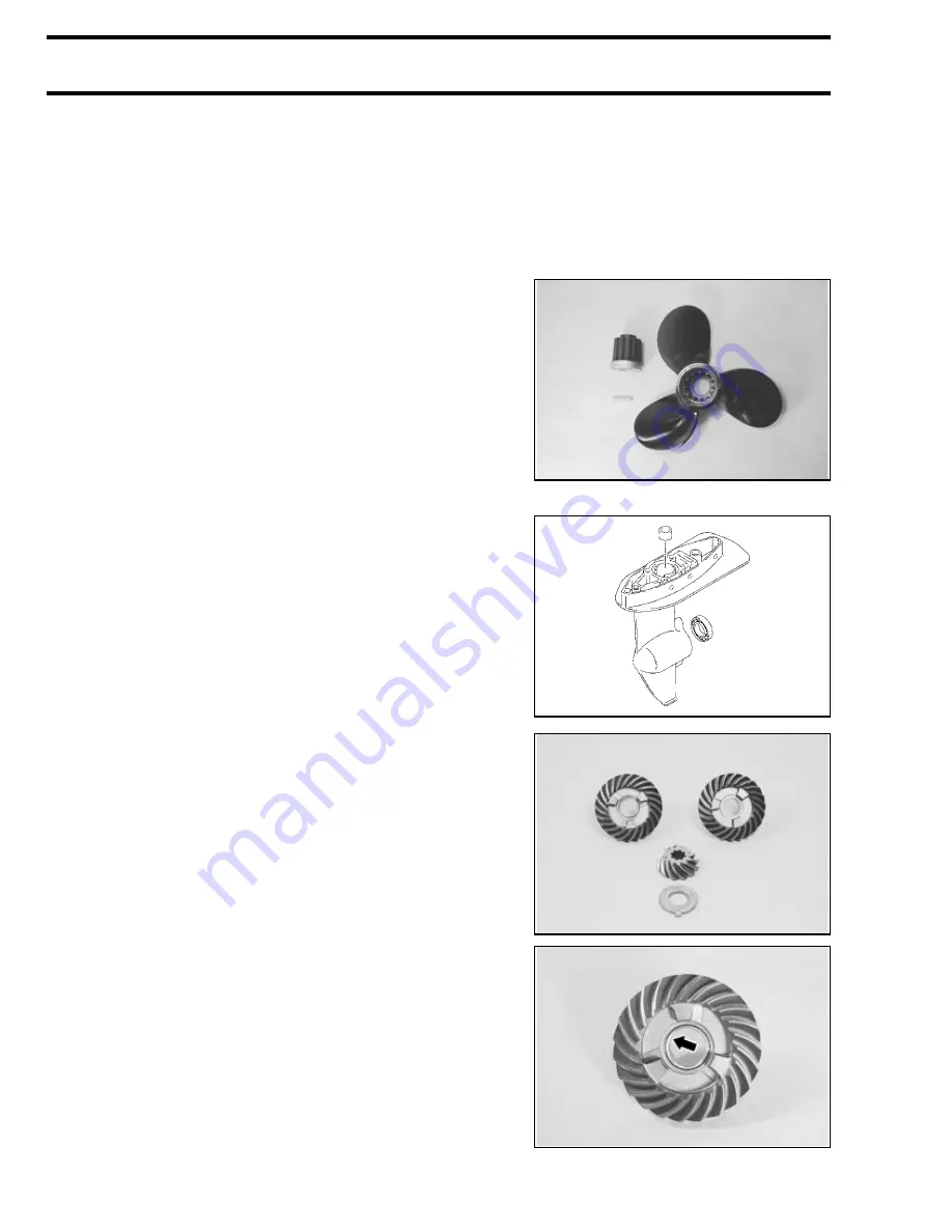
PROPELLER
•
Inspect the propeller. If bent, chipped or other damage is
found on the blades, replace or repair the propeller.
•
Inspect the propeller bushing. If excessive wear or other
damage is found on the splines, replace the bushing. If
deterioration or evidence of slipping on the rubber part,
replace the bushing.
•
Inspect proppeler shaft splines. If damage is found,
replace the shaft.
GEARCASE
•
Inspect the gearcase. If cracks or other damage is found,
replace the gearcase.
•
Visually check the forward gear bearing. If pitting, noisy,
roughness or other damage is found, replace the bearing.
•
Visually check the driveshaft bushing. If excessive wear,
pitting or other damage is found, replace the bushing.
GEAR
•
Inspect the teeth of the forward, reverse and pinion gear.
Inspect the engaging dogs of the forward and reverse
gear. If excessive wear, chipping or other damage is found,
replace.
•
Inspect the forward gear bushing. If excessive wear, pitting
or other damage is found, replace.
Содержание Johnson 4HP
Страница 1: ......
Страница 2: ......
Страница 6: ......
Страница 26: ...1 20 GENERAL INFORMATION NOTES NOTES...
Страница 50: ...3 8 IGNITION AND ELECTRICAL NOTES NOTES...
Страница 66: ...4 16 FUEL SYSTEM NOTES NOTES...
Страница 74: ...5 8 MANUAL STARTER NOTES NOTES...
Страница 116: ...6 42 POWERHEAD NOTES NOTES...
Страница 130: ...7 14 MIDSECTION NOTES NOTES...
Страница 152: ...8 22 GEARCASE NOTES NOTES...
Страница 160: ...9 8 WIRE HOSE ROUTING NOTES NOTES...
Страница 162: ...S 2...
Страница 185: ......