IntelliGear Plus
TM
Variable Speed Gearmotors and Motors
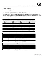
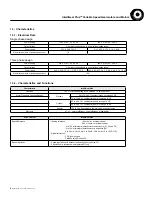
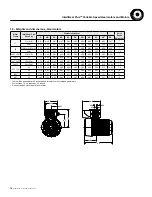
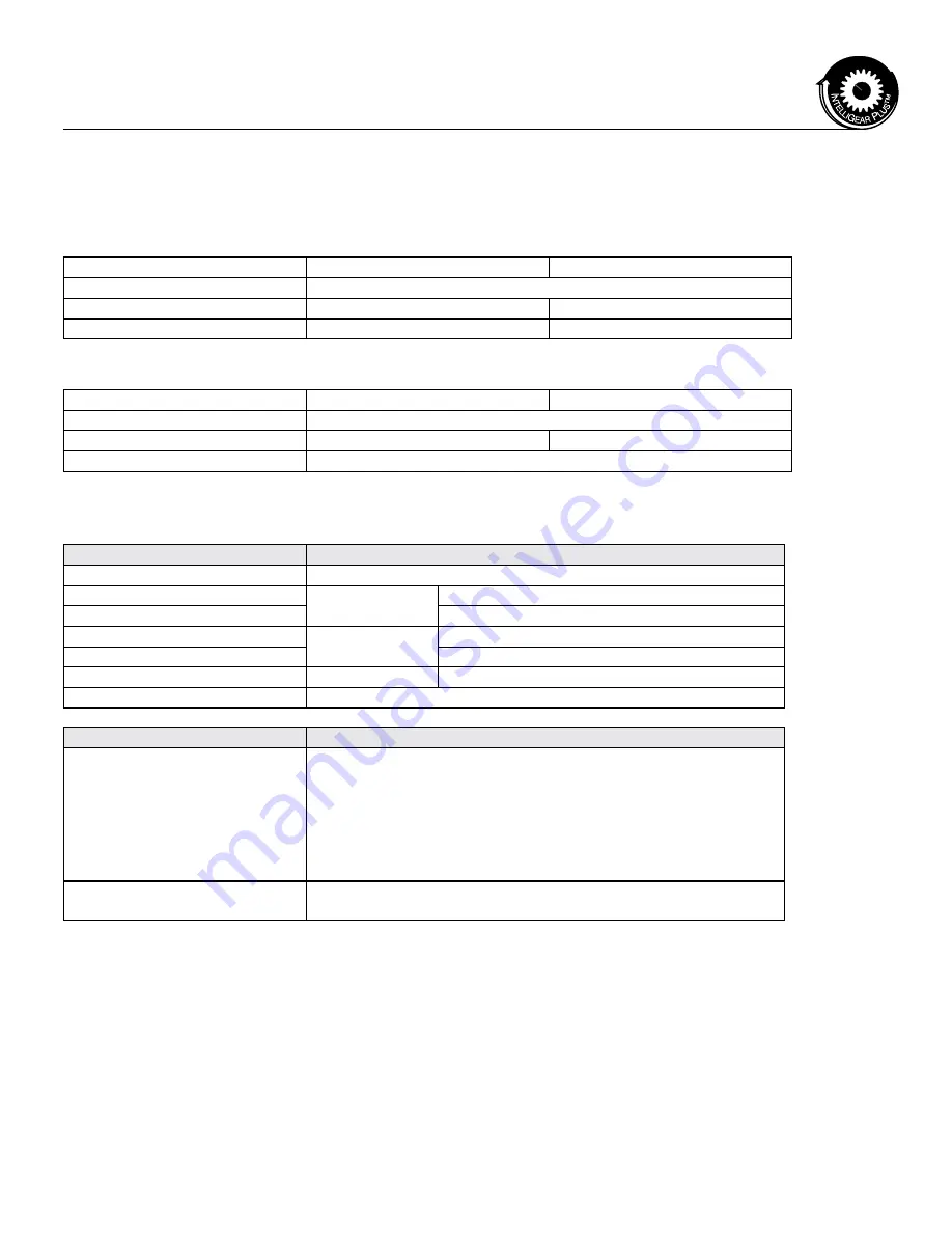
1.3 - Characteristics
1.3.1 - Electrical Data
Single phase design
Three phase design
Power supply
115 V ± 10%, 50 - 60 Hz
230 V ± 10%, 50 - 60 Hz
Output voltage
From input voltage down to (input voltage/speed range)
Power range
0.33, 0.50, 0.75 HP
0.33, 0.50, 0.75. 1.0, 1.5, 2.0 HP
Maximum numbers of power-ups per hour
10
Power supply
230 V ± 10%, 50 - 60 Hz
460 V ± 10%, 50 - 60 Hz
Output voltage
From input voltage down to (input voltage/speed range)
Power range
0.33, 0.50, 0.75. 1.0, 1.5, 2.0, 3, 5 HP
0.33, 0.50, 0.75. 1.0, 1.5, 2.0, 3.0, 5.0, 7.5, 10 HP
Maximum numbers of power-ups per hour
100
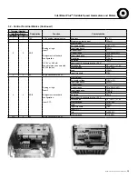
1.3.2 - Characteristics and Functions
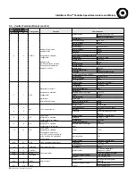
Characteristic
IntelliGear Plus
Overload
150 % of full load setting for 60 seconds, 10 times per hour
Motor Frequency Variation Ranges
Standard
60 to 10 Hz 6:1 constant torque up through 3 HP
74 to 12 Hz 6:1 constant torque for 5 through 10 HP
Optional
60 to 6 Hz 10:1 constant torque up through 1.5 HP
90 to 9 Hz 10:1 constant torque for 2 through 10 HP
Special
120 to 2 Hz depending on thermal and mechanical limits
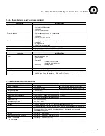
Efficiency
97.5 % x motor efficiency x gear efficiency (if applicable)
Drive Control
IntelliGear Plus
Speed Reference
"• Analog reference ( 0V or 4mA = minimum speed)
(10V or 20mA = maximum speed)
- 0 to 10V with integral potentiometer on enclosure ( P1,P2 and P3)
- 0 to 10V with integral potentiometer in enclosure (P4)
- 4 to 20 mA, 20 to 4 mA, 0 to 20 mA, 20 to 0 mA or 0 to 10 VDC (R)
• Digital references
- PD Digital Keypad
- Fieldbus using Profibus DP
Speed regulation
- Speed regulation with encoder feedback option (only size 33)
- Regulation of a reference with integrated PI loop
6
MCIM15100E • Form 9112E • Printed in USA


