III
- 12
3.2.8
Voltage Detection Circuit
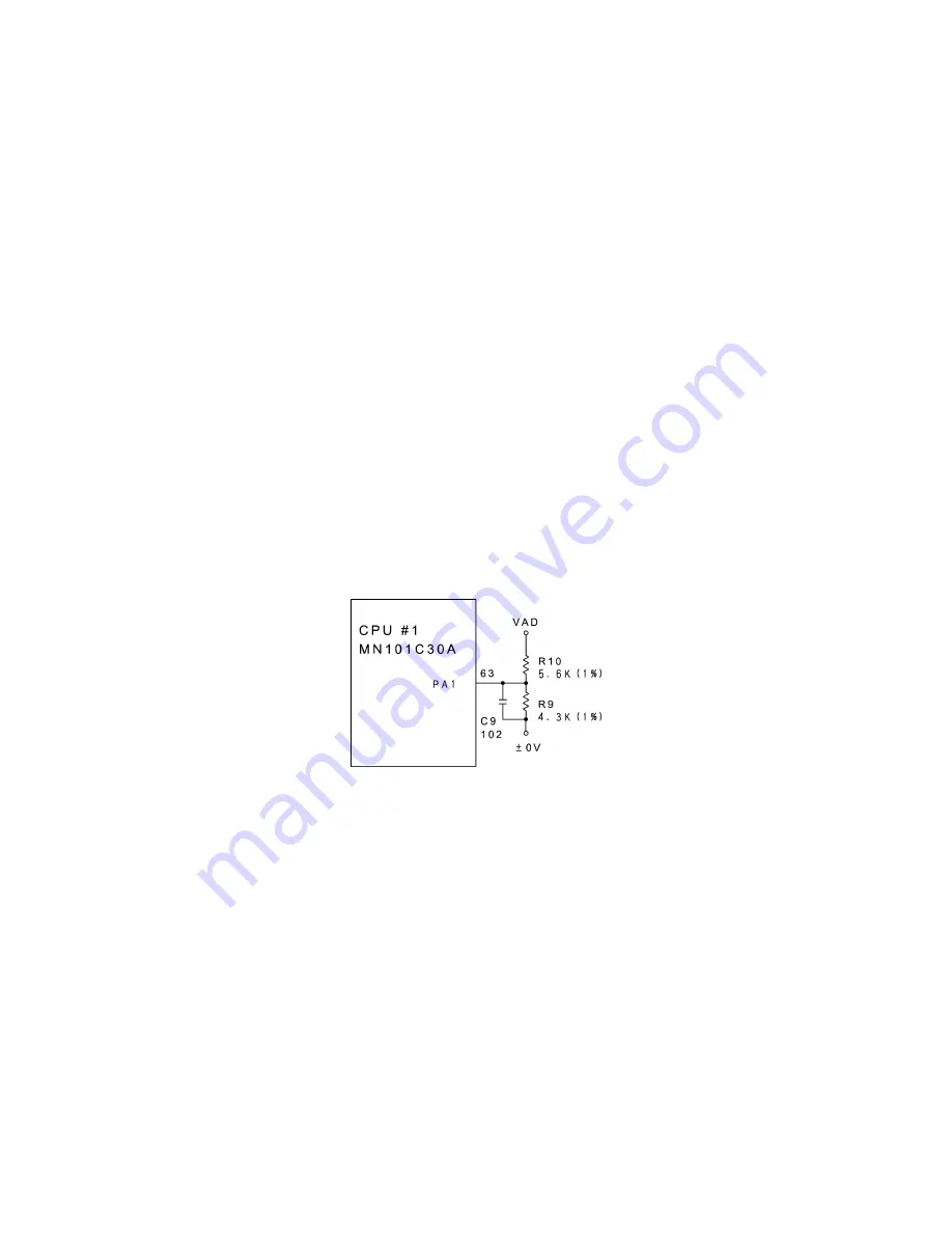
Figure 3.2-12 shows the voltage detection circuit which is composed of a resistor
network.
Voltage detection circuit
This circuit, which is composed of divider resistors R9 and R10, steps down the power
source VAD fed from dry cells or the AC adapter and feeds the output to the A/D input
port PA1 on the CPU. According to the drive source voltage, the CPU determines the
optimum head drive power.
During non-printing:
If the voltage level of the VAD drops below approx. 6.8V, the CPU immediately shuts
down the power.
Ÿ
Adapters with an output of 10.8 V or greater are designated as "high-voltage" adapters
and cannot be used for this machine. If this machine detects any high-voltage adapter
plugged in, it will power itself off.
During printing:
Ÿ
If it drops even more below approx. 5.7V, the CPU displays the "BATTERY" message
to warn you of a low battery after completion of printing.
Ÿ
If it drops below approx. 5.2V, the CPU immediately shuts down the power.
Figure 3.2-12 Voltage Detection Circuit
Содержание P-touch 65
Страница 1: ...SERVICE MANUAL MODEL P touch 65 P touch HOME HOBBY P touch One ...
Страница 2: ...SERVICE MANUAL MODEL P touch 65 P touch HOME HOBBY P touch One ...
Страница 5: ...Chapter I SPECIFICATIONS ...
Страница 9: ...I 3 Figure 1 1 2 Key Arrangement ...
Страница 11: ...Chapter II MECHANISMS ...
Страница 35: ...Chapter III ELECTRONICS ...
Страница 41: ...III 5 Figure 3 2 4 Key Scan Timing Scheme and Scanning Pulse Outputs ...
Страница 47: ...III 11 Figure 3 2 11 Timing Chart for Thermal Head Drive ...
Страница 52: ...Chapter IV TROUBLESHOOTING ...
Страница 55: ...IV 2 4 1 3 Troubleshooting Flows 1 Tape feeding failure ...
Страница 56: ...IV 3 ...
Страница 57: ...IV 4 ...
Страница 58: ...IV 5 2 Printing failure ...
Страница 59: ...IV 6 ...
Страница 60: ...IV 7 ...
Страница 61: ...IV 8 3 Powering failure Nothing appears on the LCD ...
Страница 62: ...IV 9 ...
Страница 63: ...IV 10 4 No key entry possible ...
Страница 64: ...IV 11 5 Abnormal LCD indication ...
Страница 65: ...APPENDICES Circuit Diagrams A Main PCB B Sub PCB for P touch 65 and P touch One only ...
Страница 68: ...May 2000 8V2008BE0 Printed in Japan ...


