background image

6

Installing the Printer Interface Card Driver in Windows


95 / 98

1. Make sure that the computer is turned off.

2. Connect the PC Card Cable to the Printer Interface Card.  Insert the

Printer Interface Card into your computer’s PC Card slot with the label
side face up. Be sure to insert the card fully into the slot.

3. Turn your computer on.

4. When the ‘New Hardware Found’ screen appears, select the second

option “Driver from disk provided by hardware manufacture” and
press ‘OK’.

5. Insert the supplied disk (Printer/PC Card Driver disk1) into your

floppy disk drive: (drive A in most cases) and press ‘OK’.

 Note

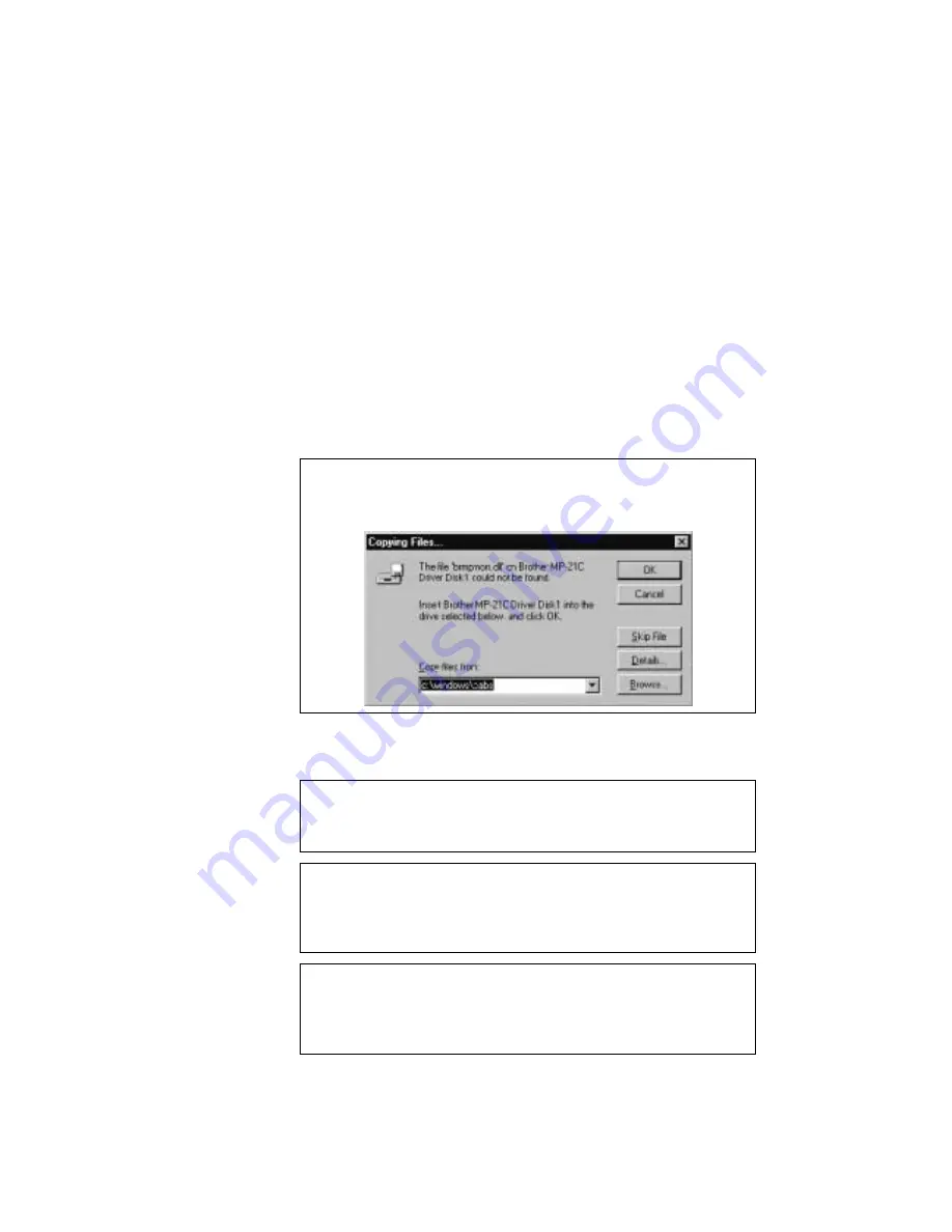
If the following screen appears, type "A:" (Or your floppy disk drive
name) and press the 'OK' button.

6. Follow the instructions that appear on the screen.

7. Restart your computer.

 Note

If you have only one PC card slot in your PC, you will need to copy the
contents of the Printer Interface Card Driver onto your hard disk.

 Note

If the Printer Interface Card is not detected by the PC, open "Device
Manager" in the "System" folder in "Control Panel". Find "Unknown
Device" and delete it.

 Note

If you are using a type of computer that allows you to connect a Floppy
Disk Drive to the printer port, remove the Floppy Disk Drive before you
restart your computer.

Содержание MP-21C

Страница 1: ......

Страница 2: ...SERVICE MANUAL MODEL MP 21C 21CDX ...

Страница 3: ...t permission in writing from the publisher Specifications are subject to change without notice Trademarks The brother logo is a registered trademark of Brother Industries Ltd Microsoft is a registered trademark of Microsoft Corporation Windows is a registered trademark of Microsoft Corporation in the U S and other countries ...

Страница 4: ...an the Print Head Purge I 14 4 11 Replacing The Ink Cartridges I 15 4 12 Recovery Function Purge I 16 5 SAFETY INFORMATION I 19 5 1 Ink Safety I 19 6 CONSUMABLES AND SERVICE ACCESSORIES I 19 6 1 Brother Special Paper I 19 6 2 Ink Cartridges I 19 6 3 ACSF and Parallel I F Cable I 20 CHAPTER II THEORY OF OPERATION 1 GENERAL II 1 1 1 Normal Interlace Processing 360dpi II 1 1 2 Super Fine Interlace Pr...

Страница 5: ...4 DISASSEMBLING AND REASSEMBLING PROCEDURE III 4 4 1 Ink Cartridge ACSF III 4 4 2 Top Cover Paper Guide Front Cover Release Plate Rear Cover III 5 4 3 Head PCB ASSY III 8 4 4 Ink Head Base Unit Print Head III 9 4 5 Bottom Cover III 12 4 6 Main PCB Power Supply PCB ASSY III 14 4 7 Paper Feed Motor ASSY III 16 4 8 Purge Unit ASSY III 18 4 9 Paper Feed Frame ASSY III 22 4 10 ACSF III 34 5 LUBRICATION...

Страница 6: ...DE IV 10 3 1 Extended Functions IV 10 3 2 Hidden Functions IV 11 3 3 Error Codes IV 13 APPENDIX A Appendix A1 Head PCB Circuit Diagram A 1 Appendix A2 Main PCB Circuit Diagram 1 3 A 2 Appendix A3 Main PCB Circuit Diagram 2 3 A 3 Appendix A4 Main PCB Circuit Diagram 3 3 A 4 Appendix A5 Cartridge Sensor Circuit Diagram A 5 APPENDIX B Appendix B Head Cleaning B 1 PR99065 ...

Страница 7: ...Chapter I FEATURES AND SPECIFICATIONS ...

Страница 8: ...C LED and MY LED I 11 4 9 4 On Off Retry Button I 11 4 9 5 Clean Button I 11 4 9 6 Printer Status I 12 4 9 7 Control Panel I 12 4 9 8 LEDs I 13 4 9 9 Printer Status I 14 4 10 How to clean the Print Head Purge I 14 4 11 Replacing the Ink Cartridges I 15 4 12 Recovery Function Purge I 16 4 12 1 Definition of Terms I 16 4 12 2 Automatic Purge I 17 4 12 3 Manual Purge I 17 4 12 4 Automatic Purge Frequ...

Страница 9: ...the Printer Interface Card Even if you use the AC adapter MP 21CDX or optional PA 21MP users only it s also easy to carry around Quietest InkJet Printer in the World The printer is so quiet less than 40dB A during printing that the printer never disturbs you while you are working No need for an AC adapter or Printer Cable The printer can take power from the notebook PC through the Printer Interfac...

Страница 10: ...1MP users only When using the Feeder you can easily load up to 30 sheets of paper When carried with the printer it fits on the top of the printer and the total size including the printer is about A4 size AC Adapter and Parallel Interface Connector MP 21CDX or PA 21MP users only When you want to print faster use the AC Adapter It will take half the printing time compared to when you are using the P...

Страница 11: ...I 3 3 CONFIGURATION 3 1 Mechanics Overview Fig 1 1 MP 21C MP 21CDX ...

Страница 12: ... control DC DC Logic 1 3 3V Logic 2 5V Motor 12V Head 13 30V Purge unit sensor Cover sensor Head driver temperature Ink cartridge sensor Stepping motor driver Stepping motor DC motor driver DC motor IEEE1284 controller EEPROM PCMCIA controller PCMCIA I F PC card 5V Head driver Head Linear encoder sensor ACSF sensor AC adapter Clean SW Power SW LED ALARM LED INK LED POWER Paper eject sensor Head co...

Страница 13: ...0 cps at 10 cpi Up to 1 3 PPM in normal print mode Up to 2 0 PPM in draft print mode Up to 2 4 PPM in Blue Black draft print mode A4 Up to 2 5 PPM in Blue Black draft print mode Ltr Print Width 203 2 mm 8 inches Print Media Liquid ink in cartridges Life Expectancy of Printer 5 years or 10 000 pages Ink Twin cartridge system separate from the print head Life Expectancy of Ink Black Cyan LC03BC 250 ...

Страница 14: ... Humidity Operating 20 to 80 without condensation Storage 5 to 95 without condensation 4 5 Dimensions and Weight Dimensions WxDxH MP 21C 50 8 x 300 x 106 mm Without ACSF MP 21CDX 90 x 305 x 140 mm With ACSF Weight MP 21C Approx 1 000g 2 2 lbs MP 21CDX Approx 1 460g 3 21 lbs 4 6 Recommended Paper Plain paper USA Xerox 4200 Europe Xerox Premier 80g m 2 or equivalent Special paper Brother Quality Coa...

Страница 15: ...2 inches 60 105g m2 16 28 lbs It is recommended to feed transparencies from the straight paper path slot or the paper feeding guide Approx 20 sheets of 75 g m2 105g m2 20 lbs 28 lbs plain paper A4 Letter Approx 30 sheets of 60 75 g m2 16 20 lbs plain paper A4 Letter Approx 20 sheets of Brother coated paper A4 Letter Cut Sheet Envelope Caliper 0 03 0 08 in 0 09 0 2mm 0 0033 to 0 0058 in 0 084 to 0 ...

Страница 16: ... 75 88 45 3 4 156 95 6 1 3 4 0 13 3 0 11 3 4 0 13 11 5 0 45 Organizer L 139 7 5 5 215 9 8 5 132 9 5 2 201 4 7 9 3 4 0 13 3 0 11 3 4 0 13 11 5 0 45 B5 176 6 9 250 9 8 169 2 6 6 210 9 2 3 4 0 13 20 0 78 3 4 0 13 20 0 78 C5 162 6 3 229 9 0 155 2 6 1 180 8 4 3 4 0 13 20 0 78 3 4 0 13 20 0 78 MONARCH 98 43 3 8 190 5 7 5 91 63 3 6 150 5 6 9 3 4 0 13 20 0 78 3 4 0 13 20 0 78 COM 10 104 78 4 1 241 3 9 5 8...

Страница 17: ...75 171 45 6 75 88 45 3 4 139 95 5 4 3 4 0 13 20 0 78 3 4 0 13 11 5 0 45 Organizer L 139 7 5 5 215 9 8 5 132 9 5 2 184 4 7 2 3 4 0 13 20 0 78 3 4 0 13 11 5 0 45 B5 176 6 9 250 9 8 169 2 6 6 210 8 2 3 4 0 13 20 0 78 3 4 0 13 20 0 78 C5 162 6 3 229 9 0 155 2 6 1 180 7 08 3 4 0 13 20 0 78 3 4 0 13 20 0 78 MONARCH 98 43 3 8 190 5 7 5 91 63 3 6 150 5 5 9 3 4 0 13 20 0 78 3 4 0 13 20 0 78 COM 10 104 78 4...

Страница 18: ... The printer is ready to feed paper Only for manual paper feed 4 9 2 Alarm LED The Alarm LED indicates a printer error status LED Printer status On Paper empty paper jam or mis feeding If a paper jam occurs Blinking The Top cover of the printer is open and should be closed so that the printer can print When the Alarm LED is on or blinking and the printer has detected an error condition refer to Se...

Страница 19: ...led correctly 4 9 4 On Off Retry Button When you press this button and when the Power LED is on the printer becomes ready to operate When the Alarm LED is on with Power LED blinking pressing this button will resume printing A paper jam or mis feed will be cleared Make sure that the Power LED is on after you press this button 4 9 5 Clean Button When you want to clean the print head press this butto...

Страница 20: ...ssed is a hidden status The printer operates in the following 3 modes Mode Description Normal mode After initialization and error detection are carried out the printer goes into normal print mode Hidden function mode Inspection mode Initialization is not carried out on the mechanical parts mechanical operation is controlled using commands and switches For factory use only PCB check mode Mechanical...

Страница 21: ... Ink empty z z Operator call Ink near empty z Ink empty z z z Cover open No alarm z Ink near empty z Ink empty z z z Purging Service call z Indicates an LED is ON Indicates an LED is OFF Indicate an LED is blinking LEDs with the same symbol means that they blink at the same speed When a service call has occurred its error type and error code are indicated using 4 bits LED1 to LED4 Refer to service...

Страница 22: ...r Status Process support mode 2 Power off This status is the power consumption save mode where only the control panel operates Buttons Power Online button Pressing this button allows the printer to become online and offline When in manual feed mode and there is no paper the printer becomes offline and does not print If this happens when using the manual feed slot load a sheet of paper the printer ...

Страница 23: ... the carriage is resting in the home position at the right hand side of the printer 3 Pull out the empty ink cartridge in the direction of the arrow Note Make sure that the Power LED is ON otherwise the ink used counter will not be cleared Fig 1 6 Caution DO NOT remove ink cartridges when you do not need to replace them Insert a new ink cartridge within a few seconds of taking out the empty ink ca...

Страница 24: ...ge The purge operation is carried out just before the first print job when more than a certain number of days have passed see below since the last purge was carried out The printer memorizes the time when the last purge was conducted in the EEPROM When the printer has been left with power off the time and date is sent from the PC just before printing by the printer driver The printer conducts the ...

Страница 25: ... the purge How to execute Purge type Remark Pressing the Clean button on the printer SP Only SP is available Clicking the Clean button in the Windows printer driver SP PP You can select SP or PP 4 12 4 Automatic Purge Frequency In case the manua l purge was carried out 3 times by pressing the Clean button on the control panel the PP begins automatically and continuously after the 3rd single purge ...

Страница 26: ...rinter is performing a purge operation 4 12 5 Purge Sequence IP SP SP SP CP SP SP IP MP SP SP CP WP SP In case no print operations are not performed in 7 days IP MP SP SP CP TP SP In case no print operations are not performed in 9 days IP WP SP In case no print operations are not performed in 6 days MP is performed after an automatic purge is carried out MP is performed before an automatic purge i...

Страница 27: ... get medical attention SKIN CONTACT Wash with water and soap or detergent INGESTION Dilute with water and if necessary get medical attention Never give anything by mouth to an unconscious person INHALATION Remove to fresh air area Help with breathing and if necessary get medical attention 6 CONSUMABLES AND ACCESSORIES 6 1 Brother Special Paper Quality Coated Paper for 360 dpi printing Letter size ...

Страница 28: ...I 20 6 3 AC Adapter ACSF and Parallel I F Cable AC Adapter and Parallel I F cable No PA21MP ASCF only No SF21MP PR99052 ...

Страница 29: ...Chapter II THEORY OF OPERATION ...

Страница 30: ...tage Control II 9 2 3 7 Home Position Detection of the Maintenance Mechanism II 9 2 3 8 Memory Circuit II 9 2 4 Head PCB II 9 2 5 Carriage PCB II 9 2 6 Carriage Sensor PCB II 9 2 7 Power Supply II 10 3 MECHANICS II 11 3 1 Overview of Printing Mechanism II 11 3 2 Print Head II 12 3 3 Ink Cartridge II 14 3 4 Head Maintenance Mechanism II 15 3 4 1 Components and Functions II 15 3 4 2 Mechanism II 15 ...

Страница 31: ...e the raster data for each pass are used for the printing operation To which pass storing buffer the binary raster data is loaded sequentially is allocated and is initially determined according to the interlace table 4 rasters of color print data and 1 raster of monochrome print data are converted to raster graphics transfer commands G Z and stored in the buffer After the above conversion TIFF com...

Страница 32: ... 3 Interlace table 4 Interlace table 5 Interlace table 6 Interlace table 7 Interlace table 8 Interlace table 1 Interlace table 2 Interlace table 3 Interlace table 4 Interlace table 5 Interlace table 6 Interlace table 7 Interlace table 8 pass2 pass3 pass3 Area covered by the printing head Fig 2 2 The printing operation is performed by repeating the following sequence 30 720 line feeding 30 nozzle p...

Страница 33: ...control DC DC Logic 1 3 3V Logic 2 5V Motor 12V Head 13 30V Purge unit sensor Cover sensor Head driver temperature Ink cartridge sensor Stepping motor driver Stepping motor DC motor driver DC motor IEEE1284 controller EEPROM PCMCIA controller PCMCIA I F PC card 5V Head driver Head Linear encoder sensor ACSF sensor AC adapter Clean SW Power SW LED ALARM LED INK LED POWER Paper eject sensor Head con...

Страница 34: ...The Head PCB has the following components 4 LEDs 1 cover sensor The head drive IC is on the Head PCB and is connected via 4 FPC cables from the head unit The Head PCB is connected to the Head FFC cable 3 Carriage PCB The Carriage PCB has 1 linear encoder sensor The Carriage PCB has a head temperature detect sensor 4 DC DC unit The power supply unit has the following functions 3 3V or 5V power supp...

Страница 35: ... F connector Fig 2 4 2 3 2 Control Panel The control panel controls two switch signal inputs and four LEDs Two out of four LEDs correspond to each of the ink cartridges The cover switch is contained in the switch panel When this switch is OFF the cover is open and printing is disabled However operations associated with cartridge replacement with the cover open are allowed SW 1 on the Main PCB func...

Страница 36: ...ncoder and its speed is controlled via the gate array by the CPU using the PWM control method The paper feed driving circuit is turned on and off by the M5VCNT signal from the CPU 4 CPU STPM0 STPM1 STPM0N STPM1N STPPWM0 STPPWM1 M5VCNT 12V P1 1 LF Driver M54676 To LF Motor G A 7 Fig 2 6 4 7 2 3 P6 P4 CPU EINT P ENC 2 P ENC 1 P DCM0 DCM1 DCM0N DCM1N To Encoder sensor on the carriage PCB To CR Motor ...

Страница 37: ...cts if there is paper or not and turns the sensor on and off When light is transmitted there is no paper The CH1 level of the sensor output is less than 2 5V without paper and 2 5V or more with paper present Pin CPU Pin CPU Fig 2 8 With paper Movable tip Movable tip PH1 PH1 Without paper Main PCB Main PCB Fig 2 9 ...

Страница 38: ...are drive data serial data signals to the head driver HCLK P and HSTB P are the clock and shift signals of the drive data signals HVDD is a head driving power supply voltage and is variable according to the output of the thermistor HDTHM P signal on the Head PCB FIRE0 N FIRE1 N FIRE2 N and FIRE3 N are signals setting the timing to apply the head driving voltage to the head actuator VDD1 is a signa...

Страница 39: ...quence and is detected when the power is turned on Refer to Fig 2 5 2 3 8 Memory Circuit Location 7 is the LSI which is the gate array to control printing Location 8 is the static RAM of 1Mb Location 5 is the EEPROM Location 6 is the reset IC Location 5 and 6 are connected to the CPU 2 4 Head PCB 4 LEDs a cover switch the head drive IC 4 head FPC connectors and 2 cartridge sensor connectors are co...

Страница 40: ...which are converted from the DC input When HVDSEL is open Connector pin 1 NC Connector pin 2 4 PCM5V Connector pin 5 7 PCM5V RET Connector pin 8 5V Connector pin 9 3 3V Connector pin 10 11 SGND Connector pin 12 HVDCUTOUT Connector pin 13 ADPT Connector pin 14 HVDSEL Connector pin 15 16 P RET Connector pin 17 12V Connector pin 18 24V ...

Страница 41: ...11 3 MECHANICS 3 1 Overview of Printing Mechanism Fig 2 12 ACSF Pick up roller ASSY Separation pad ASSY Main roller ASSY Power supply PCB Bottom cover Paper eject roller ASSY Carriage ASSY Extension guide ...

Страница 42: ...ted in the ink in the channel Thus the nozzle ejects ink drops Ink drops are propelled forwards by this action and are fired onto the paper held by the platen and form dots of the respective color This printer incorporates thirty two ink firing mechanisms per color as explained above 2 colors per head with 2 print heads 126 in total Head Specifications 1 Method PZT Xaar method with the dummy chann...

Страница 43: ... 30 V The driving voltage is controlled according to the head temperature see 2 3 6 Head Voltage Control 9 Driving pulse SP SPT or SPIT No droplet gradation control Overall cycle change 5 or less 2 µs 2 µs 2 Fire 3 Fire 2 Fire 1 µs Fire 0 When printing in the REV direction When printing is in the FWD is direction the order of the Fire 3 to Fire 0 signals is reversed Fig 2 15 PR99052 ...

Страница 44: ...eep the most suitable internal pressure for printing When operating the purge system the waste ink of all 4 colors is delivered from the Purge unit ASSY to the waste ink absorber through the waste ink tube and needle Ink Cartridge MY The basic structure of the Ink cartridge MY is the same as the Ink cartridge BC but there is no waste ink absorber The Magenta and Yellow waste ink is delivered to th...

Страница 45: ...etects the Maintenance cam position 3 4 2 Mechanisms The Maintenance cam connects the drive from the Paper feed motor to the Purge unit ASSY and rotates it The up and down movements of the suction cap the cap the wiper and the carriage locker and suction and ejection operations of the pump are performed by one rotation of the Maintenance cam 1 Suction Mechanism The suction cap is pressed on the no...

Страница 46: ...pin goes up before the suction operation to lock the carriage and goes down again before the wiping operation 5 Sensor The sensor is on during stand by It goes off when it detects the home position to start the suction operation after the Maintenance cam rotates The sensor goes on after the suction ejection and wiping operations 3 5 Sensors 3 5 1 Top Cover Sensor Fig 2 17 Top cover Cover sensor ...

Страница 47: ...per path slot or the Paper feeding guide The bottom edge of the paper Fig 2 18 Paper feeding can be from the Straight paper path slot or the Paper feeding guide Manual feeding Paper feeding starts when the Paper feed sensor turns into ON In a manual feeding the paper is fed until it hits the sensing point of the Paper eject sensor If the Paper eject sensor turns ON the paper is continuously fed fu...

Страница 48: ...til both the Paper feed sensor and the Paper eject sensor go into the OFF status During the paper eject operation if the Paper eject sensor does not turn OFF after the specified amount of paper feeding performed after the Paper feed sensor returns to the OFF status the printer feeds the paper intermittently If the Paper eject sensor still does not returns to OFF a paper jam will be detected When b...

Страница 49: ...and by home position and goes off when the Maintenance cam rotates and detects the Maintenance cam s position to start the suction operation The sensor goes on after the purge ejection wiping and capping operations are completed Fig 2 19 Maintenance sensor Cylinder ASSY Maintenance cam Head cap Flushing foam R2 Flushing foam R1 Purge unit FFC Maintenance gear 10 ...

Страница 50: ...pulley The guide shaft supports the carriage The carriage holds the timing belt The direction of the carriage motor rotation corresponds to the direction of the carriage movement The position of the carriage is controlled by the encoder strip Fig 2 20 Drive pulley Idle pulley Carriage ASSY Encoder strip Carriage guide Print head Guide bar Carriage motor ASSY Timing belt ...

Страница 51: ...he paper feeding operation and returns to the initial position and is registered by the paper feed pressure spring behind the separation roller gear Separated paper is fed to the contact point of the Main roller and the Pressure roller by the Pick up roller where the top of the paper is registered After the paper is registered the Paper feed motor is driven in the paper feeding direction normal ro...

Страница 52: ...Chapter III DISASSEMBLY AND REASSEMBLY ...

Страница 53: ...ge Unit ASSY III 18 4 8 1 Flushing Foam R1 and R2 III 20 4 9 Paper Feed Frame ASSY III 22 4 9 1 Paper Feed Motor Holder III 22 4 9 2 Arm Stopper III 23 4 9 3 Paper Eject Idle Gear 25 III 24 4 9 4 Carriage Guide III 24 4 9 5 Paper Eject Roller ASSY III 25 4 9 6 Platen Cover Flushing Foam L1 and L2 III 26 4 9 7 Main Roller ASSY III 29 4 9 8 Encoder Strip III 33 4 10 ACSF III 34 4 10 1 ACSF Support I...

Страница 54: ...such as cables PCBs and covers 4 Before handling the PCBs touch a metal portion of the equipment to discharge any static electric charge in your body or the electronic parts or components may be damaged 5 When transporting PCBs be sure to wrap them in the correct protective packaging 6 Be sure to replace self tapping screws correctly if removed Unless otherwise specified tighten screws to the torq...

Страница 55: ...needle Screw bind B M2x6 1 1 5 0 5 Min 0 5 Ink head base unit Taptite bind M26x4 2 4 5 1 Min 2 5 Print head Screw bind B M2x8 2 2 1 Min 1 Paper feed motor ASSY Taptite bind M26x4 2 4 5 1 Min 2 Purge unit ASSY Taptite bind B M3x6 4 4 1 Min 1 5 Paper feed motor holder Taptite bind M26x4 1 4 5 1 Min 2 Gear shaft 4 calking ASSY Taptite bind M26x4 1 4 5 1 Min 2 Gear frame R ACSF Taptite bind B M3x8 2 4...

Страница 56: ...ASSY Power Supply PCB ASSY 4 1 ACSF 4 10 1 ACSF Support 4 10 2 Pick up Roller Cover 4 10 3 ACSF Front Cover Pick up Roller ASSY Gear Frame R 4 10 4 Separation Pad ASSY 4 10 5 Extension Guide L and R 4 9 1 Paper Feed Motor Holder 4 9 2 Arm Stopper 4 9 4 Carriage Guide 4 9 3 Paper Eject Idle Gear 25 4 9 5 Paper Eject Roller ASSY 4 9 7 Main Roller ASSY 4 9 6 Platen Cover Flushing Foam L1 and L2 4 8 P...

Страница 57: ...For MP 21CDX remove the ACSF 2 Connect the power cord to the printer then turn the power on Release the Carriage ASSY from the sealing cap using the Service software tool 3 Remove the Ink cartridges BC and MY from the printer Note After removing the Ink cartridges DO NOT apply any vibration to the printer in order to prevent ink from leaking out of the Print head Fig 3 1 Carriage ASSY Ink cartridg...

Страница 58: ...p cover from the Front cover Note This is only necessary if the Top cover requires replacement otherwise it should be removed with the Front cover as described in section 4 2 3 Fig 3 2 4 2 2 Paper Guide Disassembly 1 Remove the Paper guide from the Platen cover Fig 3 3 Rear cover Paper guide Front cover Top cover ...

Страница 59: ... Front cover 2 Press the Front cover hook to release the lock then remove the Front cover Note Check that the Top cover sensor lever is attached to the Front cover Fig 3 4 Top cover sensor lever Rear cover Front cover Front cover Hook Screw bind M2 6x4 Black Hook Hook ...

Страница 60: ...t Fig 3 5 4 2 5 Rear Cover Disassembly 1 Remove the screw 2 Remove the Rear cover by releasing the two hooks by which the Rear cover is assembled onto the Bottom cover and then release the hook at the top of the Rear cover Fig 3 6 Shutter frame Rear cover Hook Hook Hook Release plate Screw bind M2x4 Black ...

Страница 61: ...he four Head FPC cables from the connectors one at a time 3 Remove the Cartridge sensor connector 3P from the connector on the Head PCB ASSY Fig 3 7 4 Lifting the outer edge of the PCB remove the Head PCB ASSY while pulling the hook securing the Head PCB ASSY outwards Fig 3 8 Head FPC Cartridge sensor connector 3P Chassis L Head PCB ASSY Head FFC Hook Ink head base unit Head PCB ASSY ...

Страница 62: ...ervice software tool Disassembly 1 Remove the screw securing the Waste ink needle It is fitted nearest to the removed Head PCB ASSY position Release the Waste ink tube from the three hooks Note Use caution when handling the Waste ink needle it may cause you injury Fig 3 10 Cover sensor actuator Cover sensor actuator spring Screw bind B 2X6 Waste ink needle Ink head base unit ...

Страница 63: ...head base unit be sure to remove the four protective parts fitted on the Ink needles which are positioned behind the shutters 3 Supporting the Ink head base unit move the Carriage ASSY to the position indicated in the illustration below Remove the two screws then remove the Print head and the Ink head base unit together from the Carriage ASSY Fig 3 12 Screw bind M26x4 Boss Hook Ink head base unit ...

Страница 64: ...ews 4 Insert the Print head into the Nozzle protector Note Check that the Print head is fitted correctly in the Nozzle protector Fig 3 13 Reassembly Note Check that the Carriage guide is fitted in the groove of the Carriage ASSY Refer to Fig 3 12 Nozzle protector Print head PR99066 PUSH Print head Front of the printer Back of the printer ...

Страница 65: ...o screws from the Interface connector using a precision screwdriver Fig 3 14 2 Turn the printer upside down Remove the four screws Fig 3 15 Precise screw M16x4 Interface connector Bottom cover Screw bind M2 6x4 Black Bottom cover Screw bind M2 6x4 Black ...

Страница 66: ...P Paper feed motor harness 4P Maintenance sensor FFC 3P and Encoder FFC 5P from the Main PCB ASSY Fig 3 17 Reassembly Note When attaching the Bottom cover to the printer check that the Carriage motor harness 2P is not caught between the Chassis R and the Bottom cover Main PCB ASSY Bottom cover Main PCB ASSY Carriage motor harness 2P Paper feed motor harness 4P Head FFC Encoder FFC 5P Maintenance s...

Страница 67: ...Power supply PCB ASSY from the connector on the Main PCB ASSY 2 Remove the Main PCB ASSY from the Bottom cover by releasing the four hooks 3 Release the lock of the Head FFC cable connector which is connecting the Main PCB ASSY and Head PCB ASSY then remove it from the connector on the Main PCB ASSY Fig 3 18 Main PCB ASSY Hook Hook Hook Hook Head PCB ASSY Head FFC Head FFC Power supply FFC Power s...

Страница 68: ...from the connector on the Power supply PCB ASSY Fig 3 19 Reassembly Note Insert the Power supply FFC into the connector on the Main PCB ASSY with the terminals facing upwards After inserting the Head FFC into the connector on the Main PCB ASSY lock the connector Hook Hook Hook Hook Power supply FFC Power supply PCB ASSY Bottom cover ...

Страница 69: ...s 4P to the double sided adhesive tape secure the Purge unit FFC cable with the hook Attach the Carriage motor harness 2P and Paper feed motor harness 4P to the double sided adhesive tape so that they DO NOT overlap each other DO NOT fold the Purge unit FFC cable When attaching the Bottom cover to the printer check that the Carriage motor harness 2P is not caught between the Chassis R and the Bott...

Страница 70: ...tor holder Fig 3 21 Reassembly Note Mount the Paper feed motor ASSY on the Paper feed motor holder with the Paper feed motor connector to the right 3 Remove the Paper feed motor ASSY from the Paper feed motor holder Chassis R Taptite bind M26x4 Paper feed motor connector Paper feed motor ASSY ...

Страница 71: ...be the Waste ink needle at the end of the Waste ink tube may cause you injury 4 While lifting the Purge unit ASSY remove the Maintenance gear 10 from the Bearing in the Chassis R Note Place the removed Purge unit ASSY with the Waste ink absorber face up Use caution when handling the Purge unit ASSY to prevent ink leakage Fig 3 23 Support plate Taptite bind B M3X6 Purge unit ASSY Taptite bind B M3X...

Страница 72: ...rectly into the three guides and two hooks on the Platen cover Fig 3 26 ACSF sensor actuator Platen cover Two hooks Three guides Waste ink tube Waste ink tube Waste ink tube The Waste ink tube is not fitted in any of the guides and hooks The Waste ink tube is caught between the Platen cover and Chassis center ASSY The Waste ink tube is across the ACSF sensor actuator Purge unit ASSY Purge unit ASS...

Страница 73: ... Maintenance idle gear 20 Insert the boss of the Maintenance gear 10 into the bearing of the Chassis R Refer to Fig 3 23 Fig 3 27 4 8 1 Flushing Foam R1 and R2 Disassembly 1 Remove the Flushing foam R1 and R2 from the Purge unit ASSY Fig 3 24 Platen cover Purge unit frame Purge cam Notch Protrusion Purge unit ASSY Maintenance gear 10 Maintenance idle gear 20 Flushing foam R2 Purge unit ASSY Flushi...

Страница 74: ... Reassembly Note When you replace the Flushing foam R1 and R2 the Flushing foam L1 and L2 must be replaced too After replacing the ink counter for these forms must be reset by using the Service software tool ...

Страница 75: ...sassembly 1 Remove the screw then the Earth plate and Paper feed motor holder from the Chassis R Fig 3 28 Note The Release plate Gear 10 30 and Gear 10 20 are assembled on the Paper feed motor holder Handle the Paper feed motor holder assembly carefully so as not to lose these three parts Fig 3 29 Chassis R Taptite bind M26x4 Paper feed motor holder Earth plate Gear 10 30 Release plate Paper feed ...

Страница 76: ...stopper from the Connection switching arms Fig 3 30 Reassembly Note Fit the Arm stopper over the Connection switching arms with its wider opening to the left Fig 3 31 Connection switching arm Arm stopper Narrower opening Arm stopper Wider opening Chassis R ...

Страница 77: ... Note The carriage speed auto adjustment must be done when the Carriage guide is replaced See 3 2 5 Carriage Control Parameter Adjustment Mode in Chapter 4 Disassembly 1 Remove the screws from Chassis L and Chassis R 2 Remove the Carriage guide Fig 3 33 Boss Carriage guide Boss Paper eject idle gear 25 Chassis R Taptite bind M26x4 Taptite bind M26x4 ...

Страница 78: ... 34 4 9 5 Paper Eject Roller ASSY Note After replacing Paper eject roller ASSY adjustment is need by using the Service software tool Disassembly 1 Pull the Bearing L forward to 225 degrees in order to remove the Paper eject roller ASSY from the Chassis L 2 Pull the Bearing R to 225 degrees and remove the Paper eject roller ASSY from the Chassis R and the Chassis L Fig 3 35 Platen cover Bearing L P...

Страница 79: ... Disassembly 1 Remove the Paper eject sensor actuator from the Platen cover taking care not to damage the two hooks holding the actuator Caution Use caution when handling the thin metal actuator its sharp edges may hurt you Note DO NOT bend the Paper eject sensor actuator it is thin and care is needed to avoid damaging this part Fig 3 36 Reassembly Note Attach the Paper eject sensor actuator to th...

Страница 80: ...r fingers move the Platen cover to the left then remove it Fig 3 37 3 Remove the PE sensor actuator from the Platen cover Note DO NOT bend the PE sensor actuator it is thin and care is needed to avoid damaging this part Fig 3 38 PE sensor actuator arm PE sensor actuator Platen cover Chassis center ASSY Platen cover Boss Boss ...

Страница 81: ...t be reset by using the Service software tool Insert the PE sensor actuator arm into the hole of the Platen cover Care not to bend the PE sensor actuator arm when attaching the Platen cover to the Chassis ASSY Check that the Main roller gear teeth are engaged with the gear teeth of the gear in the Gear shaft 4 calking ASSY otherwise the Platen cover will not fit correctly Fig 3 40 Flushing foam L1...

Страница 82: ... Main roller ASSY and Main roller gear 40 adjustment is need by using the Service software tool Disassembly 1 Remove the screw then Gear shaft 4 calking ASSY from the Chassis R Fig 3 42 Two grooves Chassis R Gear shaft 4 calking ASSY Platen cover ACSF sensor actuator Bottom view of the Platen cover Taptite bind M26x4 ...

Страница 83: ...sis R Secure it using the screw Fig 3 43 2 Separate the Connection switching arm from the Chassis R by pressing the end of the Connection switching arm from the other side of the Chassis R Fig 3 44 Chassis R Maintenance driving gear 16 Main roller ASSY Connection switching arm Chassis R Two grooves Gear shaft 4 calking ASSY Maintenance driving gear 40 ...

Страница 84: ...45 Reassembly Note Refit the Retaining ring to the Main roller ASSY using a slotted screwdriver while holding the shaft end of the Main roller ASSY 6 Turn the Bearing L main clockwise until its catch fits in the detented portion of the Chassis L then remove the Bearing L main Fig 3 46 Chassis L Bearing L main Chassis R Spring pin 1x5 Retaining ring Main roller gear 40 Black Paper eject idle gear 2...

Страница 85: ... fits in the detented portion of the Chassis R then remove the Release cam Note Gear 10 is assembled on the Release cam Be careful not to lose the Gear 10 9 Remove Gear 10 from the Release cam Fig 3 48 Reassembly Note Fit the catch of the Bearing R main in the detented portion of the Chassis R then turn the Bearing R main Chassis R Chassis center ASSY Main roller ASSY Bearing R main Gear 10 Chassi...

Страница 86: ...when removing the Encoder strip its sharp edges may hurt you Note DO NOT fold the Encoder strip DO NOT touch the Encoder strip surface if you touch the Encoder strip surface by accident replace it Ensure the Encoder strip is clean prior to reassembly Reassembly 1 Hook the right end of the Encoder strip on the Encoder hook 2 Run the encoder strip under the Carriage ASSY and hook the left end of the...

Страница 87: ...lling both ends of the ACSF support outwards Fig 3 50 4 10 2 Pick Up Roller Cover Disassembly 1 Remove the Pick up roller cover from the ACSF by releasing the two hooks Note Use a slotted screwdriver to release the two hooks Fig 3 50 Hook Hook ACSF front cover ACSF Pick up roller cover ACSF support ...

Страница 88: ...ler ASSY Gear Frame R Disassembly 1 Remove the ACSF front cover from the ACSF Fig 3 52 2 Remove the two screws then the Gear frame R and Pick up roller ASSY together Fig 3 53 Taptite bind B M3x8 Pick up roller ASSY Gear frame R ACSF front cover ...

Страница 89: ...SSY from the Bearing by moving it to the right 4 Remove the Gear frame R from the Pick up roller ASSY Fig 3 54 4 10 4 Separation Pad ASSY Disassembly 1 Remove the Separation pad ASSY from the ACSF Fig 3 55 Pick up roller ASSY Gear frame R Separation pad ASSY ...

Страница 90: ...III 37 4 10 5 Extension Guide L and R Disassembly 1 Remove the two screws then Extension guide R and L from the ACSF Fig 3 56 Tatptite bind M3x8 Extension guide R Extension guide L Tatptite bind M3x8 ...

Страница 91: ...rer Sesame sized pinch of grease 0 5 1 mm 3 Rice sized pinch of grease 6 mm 3 Molykote EM 30L Dow Corming Floil 946P Kanto Kasei Floil GE676 Kanto Kasei G501 Shinetsu Silicone 1 Paper feed related gears EM2 EM2 EM2 Main roller gear 40 Release plate EM2 Paper eject idle gear 15 Paper eject idle gear 25 Release cam Fig 3 57 P1 EM1 EM2 GE1 G1 ...

Страница 92: ...feed motor holder EM1 EM2 EM2 EM1 Gear 10 30 Gear 10 20 Release plate Fig 3 58 3 Purge unit ASSY EM2 Maintenace gear 10 Maintenace idle gear 20 Maintenace driving gear 16 EM2 EM2 Maintenace idle gear 20 Maintenace gear 10 Fig 3 59 Fig 3 60 ...

Страница 93: ...roller ASSY Maintenace driving gear 16 Connection switching arm Maintenace driving gear 40 Main roller gear 40 Black EM2 Bearing R Shaft of the Paper eject roller ASSY Paper eject roller gear 15 Paper eject roller ASSY EM2 Bearing L EM2 Bearing L main EM1 Appy with a blush EM2 EM2 Paper guide Fig 3 61 ...

Страница 94: ...Carriage guide G1 G1 Fig 3 62 6 ACSF Gear frame R EM2 EM2 EM2 EM2 Gear 35 On the teeth of the Paper feed gear 35 On the teeth of the Gear 12 30 Fig 3 63 Carriage guide Left Right 19 mm PR99061 12 mm 35 mm 35 mm ...

Страница 95: ...III 42 Pick up roller ASSY EM2 EM2 Fig 3 64 ...

Страница 96: ...ning the Platen cover 1 Open the top cover 2 Wipe the Platen cover with a cotton swab Fig 3 65 6 2 Cleaning the edge of the Head cap 1 Open the Top cover then insert a small clip into the hole for the cover sensor Plug the power cord to the printer then turn the power on 2 Unplug the power cord when the print head has moved from the capping position 3 Clean the edge of the Head cap with the Head c...

Страница 97: ...III 44 6 3 Cleaning the Pick up roller on the ACSF 1 Remove the Pick up roller cover 2 Clean the Pick up rollers with a cloth dampen with alcohol Fig 3 67 Pick up roller cover Pick up roller ...

Страница 98: ... 7 PACKING MP 21C Carton Partition containerboard Spacer containerboard Styrofoam Styrofoam Carton User s manual Quick setup guide Floppy disks PC interface card PC interface card cable Ink cartridge Fig 3 68 ...

Страница 99: ...ard PC interface card cable Printer interface cable AC adapter Spacer containerboard Styrofoam Styrofoam Carton Carton SF 21 ACSF cushioning material SF 21 ACSF User s manual Quick setup guide Floppy disks PC interface card Ink cartridge Fig 3 69 ...

Страница 100: ...Chapter IV TROUBLESHOOTING ...

Страница 101: ...ons IV 10 3 1 1 EEPROM Reset Mode IV 10 3 2 Hidden Functions Inspection Mode IV 11 3 2 1 EEPROM All Area Reset Mode IV 11 3 2 2 Sensor Check Mode 1 IV 12 3 2 3 Sensor Check Mode 2 IV 12 3 2 4 Head Stopper Height Check Mode IV 12 3 2 5 Carriage Control Parameter Adjustment Mode IV 12 3 2 6 Purge Air Pressure Measure Mode IV 12 3 2 7 Printer Setting Mode IV 12 3 3 Error Codes IV 13 3 3 1 Operator Ca...

Страница 102: ...s not exposed to ammonia fumes or other harmful gases 5 The printer is not located in a hot or humid area such as near water or a humidifier 6 The printer is not exposed to direct sunlight 7 The room is well ventilated 2 Paper Check if 1 A recommended type of print paper is used If the paper is too thin or tends to curl paper jams or paper feed problems may occur or prints may be blurred 2 The pri...

Страница 103: ...orrectly 2 Repeat the head purging operation several times 1 2 Basic Procedure 1 Check the error lamps according to the procedures in the inspection mode as described later in this section 2 If any incorrect image is found refer to the image defect description in this section ...

Страница 104: ...rrect voltage present at the outlet NO Inform the user that the correct voltage is not supplied at the outlet Is the PC card cable connected securely NO Connect the cable securely Power plug 2 Is the AC adapter power cord securely plugged into the outlet NO Plug the power cord securely into the outlet Is the Printer interface card securely inserted into the PCMCA card slot on the PC NO Install the...

Страница 105: ... the AC adapter Power supply FFC 2 Is the Power supply FFC cable connected to the Main PCB ASSY and the Power supply PCB ASSY NO Connect it to the both PCBs securely Power supply unit 3 Measure the voltage between the terminals Do the measured voltages satisfy the value in the table below The voltage for P3 18 depends on the operating temperature NO Replace the power supply unit PCB lead lead Volt...

Страница 106: ...s P4 2 Is the Encoder FPC cable P6 securely connected to the Main PCB NO Connect it securely Encoder strip 1 Encoder strip is contaminated with dust YES Blow the dust out with an air brush Encoder strip is contaminated with oil or ink YES Clean it with alcohol then reassemble it If the problem still remains replace it with a new one Carriage motor 2 Check the Carriage motor operation referring to ...

Страница 107: ...in PCB 4 Is the paper guide film incorrectly stuck to the paper holder ASSY Is the paper guide film bent Is the Paper holder ASSY bent YES Replace the Paper holder ASSY Ejecting paper 1 Is the Paper eject sensor actuator fitted correctly NO Refit it correctly 2 Is the Paper eject sensor actuator bent YES Replace it 3 Is the Paper eject sensor working NO Replace the Main PCB ACSF Feeding paper 1 Is...

Страница 108: ...te ink tube is routed correctly If the Purge unit is assembled correctly Check the following components Ink cartridge Main PCB Head PCB Power supply PCB Dark Check the following Monitor calibration has been carried out Try purging several times Check the paper feed related rollers If the Purge unit is assembled correctly If not colors are mixed and a dark color is generated Check the following com...

Страница 109: ...ve dust or air bubbles from the nozzles If any cartridges have run out of ink Replace the carriage PCB Check the connection of the Head FFC CABLE and the Head FPC cable Replace the Main PCB Check if the Purge unit is attached properly Check the routing of the Waste ink tube White horizontal streaks Perform the head cleaning operation several times to remove dust or air bubbles from the nozzles Rep...

Страница 110: ...tting is selected in the printer driver 2 1 3 PC driven printing Trouble Check PC driven printing is impossible Check the following Connection of the Parallel interface cable to the printer and the host PC Connection of the AC adapter If the Printer interface card is inserted securely If the PC card cable connecting the Printer interface card CI 100 and the printer is connected securely If the Was...

Страница 111: ...p cover closed Immediately after entering this mode the all LEDs blink By pressing the Power button EEPROM user area reset will be executed Although it will return to the ready status after reset it is necessary to press the Power button The following information is stored in the user area The carriage speed settings The counter for the amount of the ink consumed and the waste ink The time when th...

Страница 112: ...ge Control Parameter Adjustment Mode Purge Air Pressure Measure Mode Printer Setting Mode 3 2 1 EEPROM All Area Reset Mode DO NOT USE Initializes the all area of the EEPROM If all areas are cleared the printer will not work All LEDs blink once Ink MY LED lights Ink BC LED lights Ink BC MY LED light Clean Clean Clean Clean Power Enter the inspection mode Power EEPROM All Area Reset Mode Power Senso...

Страница 113: ...ttached to the head cap on the Purge unit ASSY 3 2 5 Carriage Control Parameter Adjustment Mode Immediately after entering this mode the carriage speed auto adjustment will be executed and correct parameters will be set automatically If any abnormal too slow or too fast speed is detected there will be a carriage speed auto adjustment error indicated by LED indication Refer to section 3 3 2 Service...

Страница 114: ... and press the Power button to make the printer online Ink cartridge BC unloaded error Ink cartridge BC is not installed Install the Ink cartridge BC Ink cartridge sensor failure Replace the Ink head base unit Ink cartridge MY unloaded error Ink cartridge MY is not installed Install the Ink cartridge MY Ink cartridge sensor failure Replace the Ink head base unit Ink cartridge BC near empty Ink car...

Страница 115: ... Replace the Main PCB 01 03 Incorrect carriage interrupt command Carriage interrupt command was issued when the Carriage ASSY is in a stop position Replace the Main PCB 01 04 Carriage movement error The carriage moves only less than 1 2 inch Adjust the mechanical portion related to the Carriage ASSY Replace the Main PCB 01 05 Low carriage speed error The speed is not stable due to foreign material...

Страница 116: ...gn material inside the printer The Carriage ASSY cannot move smoothly Counter brake too strong Adjust the mechanical portion related to the Carriage ASSY Replace the Encoder strip 01 0A Carriage speed error The carriage ASSY cannot gain enough speed due to foreign material The Carriage ASSY cannot move smoothly Adjust the mechanical portion related to the Carriage ASSY Replace the Encoder strip 01...

Страница 117: ...ace the Purge unit ASSY 02 05 Maintenance protrusion The Maintenance gear 10 is not assembled correctly The Print head is not installed correctly to the Carriage ASSY Check the Maintenance gear 10 is assembled correctly Refer to Fig 3 27 Adjust the mechanical portion related to the chassis 03 01 Head power supply error At power on or in sleep mode Head voltage is detected when the Print head shoul...

Страница 118: ...e ink full status Replace the Flushing form L1 L2 and the Flushing form R 1 R 2 After replacing reset the ink counter for them by using the Service software tool 05 01 External RAM error There is a RAM Read Write error at power on Replace the Main PCB 05 02 Internal ROM error There is a ROM Check sum error Replace the Main PCB 05 03 EEPROM error There is a Read Write error Replace the Main PCB 05 ...

Страница 119: ...IV 18 LED INDICATING THE ERROR Example ROM error Power LED Alarm LED Ink BC LED Ink MY LED A lapse of time ON OFF ...

Страница 120: ...Appendix ...

Страница 121: ...uit Diagram A 1 Appendix A2 Main PCB Circuit Diagram 1 3 A 2 Appendix A3 Main PCB Circuit Diagram 2 3 A 3 Appendix A4 Main PCB Circuit Diagram 3 3 A 4 Appendix A5 Cartridge Sensor Circuit Diagram A 5 2 Appendix B Appendix B Head Cleaning B 1 PR99065 ...

Страница 122: ...Appendix 1 Head PCB Circuit Diagram CODE UJ7041000 MPHEAD SCH01 NAME A 1 ...

Страница 123: ...Appendix 2 Main PCB Circuit Diagram 1 3 CODE UJ7040000 MPMAIN SCH01P1 NAME A 2 ...

Страница 124: ...Appendix 3 Main PCB Circuit Diagram 2 3 CODE UJ7067000 MPMAIN SCH01P2 NAME A 3 ...

Страница 125: ...Appendix 4 Main PCB Circuit Diagram 3 3 CODE UJ7068000 MPMAIN SCH01P3 NAME A 4 ...

Страница 126: ...Appendix 5 Cartridge Sensor Circuit Diagram A 5 CODE UJ7061000 MPCTRG SCH01 NAME ...

Страница 127: ...e IL cartridges BC and MY The printer having this refurbishing needs to be connected to a PC running MOBILEPAD Preparation 1 Make sure that the power is off on the printer for preparation 2 Remove the Ink cartridges BC and MY from the printer Fig B 1 3 Install the cleaning cartridges IL cartridge BC and MY Connect the power cord and the parallel I F cable to the printer Then insert a small clip in...

Страница 128: ...ce in height between the Print head nozzles and the surface of the Initial liquid must be in the range 0 50 mm It may needs an additional N Purge several times more after carrying out the P Purge Cleaning the Print Head 6 Make sure that the power is off on the printer to be cleaned 7 Remove the IL cartridges from the printer for the preparation Fig B 4 IL cartridge MY IL cartridge BC IL tube IL tu...

Страница 129: ... details of the Printer setting mode 10 Run the MOBILEPAD on the PC Click Tool Control Initial Liquid button in order to take all remaining ink out of the printer and circulate the Initial liquid for the print head cleaning Fig B 5 Note The difference in height between the Print head nozzles and the surface of the Initial liquid must be in the range 0 50 mm IL cartridge MY IL cartridge BC IL tube ...

Страница 130: ...operation the Print head moves fully to the right hand side of the printer automatically Check if the Encoder strip is contaminated with ink oil or dust If the Encoder strip is contaminated clean it with the Head cleaner stick 13 Place a Clean wiper head next to the ink suction cap as shown below Fig B 7 Ink ejection cartridge MY Ink ejection cartridge BC Waste ink tube Waste ink bottle Print head...

Страница 131: ...n wiper head it is likely to push the Clean wiper head out of its position Please move the carriage while holding the Clean wiper head in position with tweezers Fig B 10 Print head Print head Carriage Fig B 8 Fig B 9 Print head Clean wiper head Tweezers Clean wiper head Clean wiper head Clean wiper head ...

Страница 132: ...EPAD Then automatically the Print head returns to the capping position Remove the clip from the Cover sensor and close the Top cover Note The Seal rubber fitted in the adapter at the end of the IL tube should be replaced with new one after it has been used 3 times The Seal rubber is supplied as a spare part with the number ZA0726001 Procedure for replacing the Seal rubber 1 Remove the IL cartridge...

Страница 133: ...nsert a new Seal rubber into the adapter and refit the adapter into position in the IL cartridge Note To avoid unnecessary air bubble replacement should be done below the level of the Initial liquid so that initial liquid comes up to the position of the Seal rubber 4 Close the cover ...

Страница 134: ...R Mar 99 5H1002BE0 ...

Страница 135: ...ter varies by model Follow the order of setting up as shown in the chart below MP 21CDX MP 21C Printer Interface Card Parallel Cable Optional PA 21MP Page A Printer Interface Card 1 1 4 B PC Card Cable 2 2 7 C Parallel Cable 1 1 8 D Ink 3 3 2 2 10 E Printer Driver 4 4 3 3 13 The product names in this guidebook are trademarks or registered trademarks of each manufacturer The specifications are subj...

Страница 136: ...UJ5394001 A Printed in Japan ...

Страница 137: ...e the protective parts Fig 1 Removing the Protective Parts 2 Check and see that you have all the items shown below Fig 2 Components in the Printer Carton Box PC Card Cable User s Guide Quick Setup Guide Parallel Interface Cable MP 21CDX only Floppy Disks AC adapter 100V MP 21CDX only Printer AC adapter 200V MP 21CDX only Printer Interface Card CI 100 PC Card Auto Cut Sheet Feeder MP 21CDX only Ink...

Страница 138: ...ct printer operation The steps required for setting up the printer varies by model Follow the order of setting up as shown in the chart below MP 21CDX MP 21C Printer Interface Card Parallel Cable Optional PA 21MP Page A Printer Interface Card 1 1 4 B PC Card Cable 2 2 7 C Parallel Cable 1 1 8 D Ink 3 3 2 2 10 E Printer Driver 4 4 3 3 13 Computer Requirements The following are the minimum computer ...

Страница 139: ...l SF 21MP users only 2 MP 21CDX or optional PA 21MP users only Top Cover PC Card Cable Ink Cartridges LC03BC LC03MY Printer Interface Card CI 100 Release Lever AC Adapter Connector Paper Feeding Slot Guide Auto Cut Sheet Feeder 1 AC Adapter 2 Parallel Interface Cable 2 Straight Paper Path Slot Print Head Printer Stand ...

Страница 140: ...battery power left If you remove the printer cable or turn the printer off while you are inserting the Printer Interface Card into the PC Card slot and the printer does not work correctly after that remove the Printer Interface Card from the slot and insert the card again and re start the Printer Interface Card Driver installation Before you install the PC Card Driver be sure to set the Power Save...

Страница 141: ...e Command Line box 7 Choose the OK button or press the Enter key 8 Follow the installation instructions that appear on the display monitor 9 When the installation is complete remove the disk from your floppy disk drive 10 Restart your computer 11 Turn off your computer Note The Config sys file and Autoexec bat file in your system have been changed The originals are saved as Config up1 and Autoexec...

Страница 142: ...iver disk1 into your floppy disk drive drive A in most cases and press OK Note If the following screen appears type A Or your floppy disk drive name and press the OK button 6 Follow the instructions that appear on the screen 7 Restart your computer Note If you have only one PC card slot in your PC you will need to copy the contents of the Printer Interface Card Driver onto your hard disk Note If t...

Страница 143: ...er You can connect the printer through the Printer Interface Card or through the Parallel Interface cable MP 21CDX or PA 21MP users only How to connect the PC card cable to your computer and printer 1 Connect the PC Card Cable to the printer Fig 7 Connecting the PC Card Cable ...

Страница 144: ...ers only Note Only the MP 21CDX model is shipped with an AC Adapter and Parallel Interface Cable If you would like to purchase them as an option the order number is PA 21MP 1 Connect the AC Adapter to your printer and plug it into the mains Fig 8 Connecting the AC Adapter 2 Connect the Parallel Interface Cable to the printer Fig 9 Connecting the Parallel Interface Cable ...

Страница 145: ...ote This printer does not support ECP mode If the printer port is set as an ECP port change it to be a bi directional port See your PC s manual for how to change the printer port 1 Click Start and select Printer from the Setting tab 2 Click the right mouse button on the MP 21C icon and click Properties 3 Click the Details tab and select LPT1 from the Print to the following port drop down list ...

Страница 146: ...at the printer will be stable 2 Make sure that the LEDs are on If the LEDs are off press the On Off button to turn the printer on Open the top cover Fig 11 Open the Top Cover Warning DO NOT push the shutter with your fingers Sharp pins are in the Ink Cartridge Slot If you touch them it might cause injury Note If the LEDs do not come on even after you pressed the On Off button go back to A and B an...

Страница 147: ...lot using both hands Make sure that the BC LED turns off Fig 12 Install BC Ink Cartridge Caution Be sure to insert the ink cartridge securely Do not push down on the printer when you install the ink cartridges 5 Repeat actions 3 to 4 and install the LC03MY ink cartridge into your printer and make sure that the MY LED goes off Fig 13 Install MY Ink Cartridge ...

Страница 148: ...t The print head may be damaged if you install ink cartridges other than Brother original or if you use refilled ink cartridges You might void your warranty Do not insert or remove ink cartridges while the printer is doing the following printing cleaning the print head when all the LEDs are blinking in turn feeding or ejecting paper When you insert ink cartridges place the printer on a flat surfac...

Страница 149: ... driver from the supplied disks into Windows 95 98 1 Make sure that your computer is on 2 Make sure that your printer is on Note If the New Hardware Found screen appears press the Cancel button 3 Click the Start button and choose Run 4 Insert the supplied disk for Windows 95 98 Printer PC Card Driver disk 1 into your floppy disk drive drive A in most cases ...

Страница 150: ...r key Note If you use a drive other than drive A type the drive name in the Copy manufacturers files from box on the screen 6 Follow the instructions that appear on the screen 7 When installation is complete remove the disk from the drive 8 Restart your computer ...

Страница 151: ...t Windows 3 1 2 Insert the supplied disk Printer PC Card Driver disk 1 into your floppy disk drive A or drive B 3 Choose Run from the File menu in the Program Manager 4 Type A SETUP drive A in most cases in the Command Line box Fig 14 Windows 3 1 screen 5 Choose the OK button or press the Enter key 6 Follow the instructions that appear on the display monitor 7 When the installation is complete rem...

Страница 152: ...the screen 4 Click OK to save the settings After you have installed the printer drivers try the Test Print from the printer driver as follows Note When the color level and balance does not match exactly select the ones that are the closest Test Print 1 Select Maintenance from the MP 21C series group in Windows 2 Click Test Print Note When you do the Test Print insert A4 or Letter size plain paper ...

Страница 153: ...ut select the pattern number which looks most like Fig 15 for both slow speed mode and fast speed mode Fig 15 Good Sample Fig 16 Bad Sample Note If you are not sure which number pattern is the right one select the one where the short and long vertical lines on the adjustment pattern are matched or the closest If you can find more than one pattern in which the short and long vertical lines are matc...

Страница 154: ...other Mobile Full Color Inkjet Printer MP 21C CDX User s Guide Please read this manual thoroughly before using the printer Keep this manual in a convenient place for quick and easy reference at all times ...

Страница 155: ...tridges Push the On Off button to turn the printer off Fig 0 1 Turning the Printer off 2 Turn your computer off and remove the Printer Interface Card from the computer Remove the PC Card cable from the printer and from the Printer Interface Card Remove the AC Adapter and Parallel Interface Cable if connected MP 21CDX or PA 21MP user only Fig 0 2 Remove the Cable 3 Pack the printer in the original ...

Страница 156: ... Our BBS supports modem speeds up to 14 400 8 bits no parity 1 stop bit Fax Back System Brother Customer Service has installed an easy to use Fax Back System so you can get instant answers to common technical questions and product information for all Brother products This is available 24 hours a day 7 days a week You can use the system to send the information to any fax machine not just the one yo...

Страница 157: ...UJ5351001 Printed in Japan ...

Страница 158: ...and a four digit number for your password Our BBS supports modem speeds up to 14 400 8 bits no parity 1 stop bit Fax Back System Brother Customer Service has installed an easy to use Fax Back System so you can get instant answers to common technical questions and product information for all Brother products This is available 24 hours a day 7 days a week You can use the system to send the informati...

Страница 159: ...nual has been compiled and published covering the latest product s descriptions and specifications The contents of this manual and the specifications of this product are subject to change without notice Brother reserves the right to make changes without notice in the specifications and materials contained herein and shall not be responsible for any damages including consequential caused by relianc...

Страница 160: ...rinter properly or prevent damage to the printer Note Indicates notes and useful tips to remember when using the printer To Use the Printer Safely Warning DO NOT put your hands into the printer while it is printing to avoid causing injury Fig 0 1 Inside the Printer Warning Keep the ink cartridges away from children If ink is swallowed drink plenty of water The ink contains no harmful substances bu...

Страница 161: ...e injury Warning DO NOT push the shutters in the ink cartridge slot with your fingers There are sharp pins inside the Ink Cartridge Slot If you touch them it might cause injury Printer Do s and Don t for Optimum Print Quality Caution DO NOT touch the nozzles and the print head DO NOT move the print head by hand or remove the print head from the printer Caution During thunderstorms push the On Off ...

Страница 162: ... Caution Do not disassemble the printer Caution DO NOT remove the Printer Interface Card PC card cable or AC Adapter if connected MP 21CDX or optional PA 21MP users only while the printer LEDs are on or blinking Caution When you carry the printer in your car put the printer in a protective bag or wrap the printer in a cloth Caution When you carry the printer put the printer in a plastic bag ...

Страница 163: ...ely before attempting to print Caution If you drop the printer check that there are no broken parts If you find some parts broken consult your dealer or our authorized service representative Note We recommend you select the status monitor ON when you use the printer ...

Страница 164: ... air do not put the printer in your suitcase Carry the printer onto the aircraft as hand baggage Caution When you carry the printer keep the ink cartridges installed Note If you take the printer and AC adapter abroad make sure that the power plug and the voltage requirements of the printer are correctly matched Note It is recommended that you carry spare Brother Ink Cartridges when you travel with...

Страница 165: ...out Brother Special Glossy Paper 2 5 LOADING PAPER 2 6 How to Load Paper in the Paper Feeding Slot 2 6 How to Load Paper in the Straight Paper Path Slot 2 7 How to Load Envelopes in the Straight Paper Path Slot 2 8 How to Load Paper in the Auto Cut Sheet Feeder MP 21CDX or optional SF 21MP users only 2 9 CHAPTER 3 CONTROL PANEL LED AND BUTTONS 3 1 LEDs 3 1 Buttons 3 3 CHAPTER 4 MAINTENANCE CLEANIN...

Страница 166: ...PAPER JAMS 5 3 How to clear paper jams 5 3 Q A 5 5 Setting Up the Printer Hardware 5 5 Setting Up the Printer for Windows 5 6 Paper Handling 5 7 Printing 5 8 Print Quality 5 9 APPENDIX PRINTER SPECIFICATIONS Appendix 1 Printing Appendix 1 Controller Appemdix 1 Electrical and Mechanical Appendix 2 Print Media Appendix 2 ...

Страница 167: ...l interference in a residential installation This equipment generates uses and can radiate radio frequency energy and if not installed and used in accordance with the instructions may cause harmful interference to radio communications However there is no guarantee that interference will not occur in a particular installation If this equipment does cause harmful interference to radio or television ...

Страница 168: ...h EN55022 CISPR Publication 22 Class B Before this product is used ensure that you use a double shielded interface cable with twisted pair conductors and that is marked IEEE1284 compliant The cable must not exceed 1 8 metres in length IMPORTANT For Your Safety When you use an AC Adapter with this printer be sure to use only the Brother option part number AD 100MP 100V or AD 200MP 200V Geräuschemis...

Страница 169: ...MINAL WHICH IS MARKED WITH THE LETTER E BY THE EARTH SYMBOL OR COLOURED GREEN OR YELLOW The wires in the mains cord are coloured in accordance with the following code Blue Neutral Brown Live The colours of the wiring in the power lead of this AC Adapter may not correspond with the markings which identify the terminals in your plug If you need to fit a different plug proceed as follows Remove a len...

Страница 170: ...lowing normative documents EMC EN 55022 Class B EN 50082 1 following the provisions of the Electromagnetic Compatibility Directive 89 336 EEC as amended by 91 263 EEC and 92 31 EEC and that the AC Adapter as supplied with this system conforms with EN 60950 This system also follows the provisions of the Low Voltage Directive 73 23 EEC Issued by Brother International Europe Ltd European Technical Se...

Страница 171: ...etup Guide to set up your printer and connect it to your computer It also contains information about setting up your computer for your printer by installing the printer driver 2 Read the Users Guide to obtain information about the following CHAPTER 1 Introduction CHAPTER 2 Paper Handling CHAPTER 3 Control Panel CHAPTER 4 Maintenance CHAPTER 5 Troubleshooting APPENDIX INDEX ...

Страница 172: ...optional SF 21MP users only 2 MP 21CDX or optional PA 21MP users only Top Cover Ink Cartridges LC03BC LC03MY Paper Release Lever AC Adapter Connector Paper Feeding Slot Guide Auto Cut Sheet Feeder 1 AC Adapter 2 Parallel Interface Cable 2 Straight Paper Path Slot PC Card Cable Printer Interface Card CI 100 Print Head Printer Stand ...

Страница 173: ... by 720 dpi resolution When you print on Brother special coated paper and glossy paper you can get excellent high resolution output Two color print mode When you select this mode through the printer driver you can print the color output in two colors You can select Black Cyan Black Magenta or Black Yellow Low Running Cost You don t have to throw the print head of your printer away every time you h...

Страница 174: ...35 C 50 F to 95 F Ambient humidity 20 to 80 without condensation Use the printer in a ventilated room Place the printer on a flat horizontal surface Keep the printer clean Do not place the printer in a dusty place Do not place the printer where it is exposed to direct sunlight Use a blind or a heavy curtain to protect the printer from direct sunlight when the printer is unavoidably set up near a w...

Страница 175: ...rs only Cut sheet Coated Paper for 360 dpi printing A4 Letter Executive Legal 1 B5 30 sheets of 75 g m2 Coated Paper for 720 dpi printing A4 Letter Executive Legal 1 B5 20 Transparencies A4 Letter 3 Glossy paper A4 Letter Envelopes DL COM 10 Monarch B5 C5 2 Organizer K L Paper Weight Range From Paper Support 60 to 105 g m 2 16 to 28 lb From Straight Paper Path 60 to 157 g m 2 16 to 42 lb Auto Cut ...

Страница 176: ... it is possible to stain your hands or clothes if you touch the surface of the transparency immediately after it is printed out We recommend you load transparencies from the paper feeding slot Remarks Use a recommended type of paper especially plain paper for optimum printing For more information on paper specifications consult your nearest authorized sales representative or the place you purchase...

Страница 177: ... 0 45 11 5mm 0 45 3mm 0 12 20mm 0 78 20mm 0 78 20mm 0 78 20mm 0 78 Unprintable Area Non Guaranteed Print Area Fig 2 1 Printable Area The following types of paper and envelopes are not recommended for use Damaged curled wrinkled or irregularly shaped paper and envelopes Extremely shiny or highly textured paper and envelopes Envelopes with clasps Envelopes of baggy construction Envelopes not sharply...

Страница 178: ...ity When using these papers please follow the notes below There is a surfaced side and non surfaced side to the paper and it is specially coated only on the surfaced side Therefore when loading paper in the printer make sure that the whiter side the coated surface is facing up DO NOT touch the coated side of the paper as it will absorb water and perspiration easily and might cause decreased output...

Страница 179: ... glossy paper as water or perspiration will stain the surface DO NOT touch the printing side of the paper You should use the glossy paper in normal office environmental conditions Temperature 15 25 C 59 77 F Humidity 40 60 After finishing printing a page remove each sheet of paper immediately and place it face up on a flat surface until it is completely dry DO NOT place anything on the printed sid...

Страница 180: ...er Feeding Slot Guide looking at the printer from the front Fig 2 3 Loading Paper Note About 2 seconds after you insert the paper the printer feeds the paper and then reverse feeds the paper a little the printer is now ready to print Hold the paper until the printer picks up the paper correctly If the paper does not load straight open the top cover and pull the release lever Pull the paper out clo...

Страница 181: ... the printer from the front Be sure to adjust the paper to the mark below Fig 2 4 Loading Paper in the Straight Paper Path Slot Caution Make sure you insert paper into the Paper Feeding Slot straight so that the paper does not skew Be sure to adjust the paper setting in the printer driver Load thick paper and envelopes from the straight paper path slot When the printer is in Auto Power off mode th...

Страница 182: ... side face up When you print on envelopes be sure to load them with the short edge downwards with the flap to the left hand side when you view the printer from the front When an envelope is curled straighten it before printing Fig 2 6 Straighten the Envelopes Fold the flap securely with a pen or with your finger before loading envelopes Fig 2 7 Fold the flap Make sure that the amount of curl of th...

Страница 183: ...uto Cut Sheet Feeder are closed 2 Fit the Auto Cut Sheet Feeder onto the printer Push the latches securely until you hear them click into the lock position Fig 2 9 Fit the Auto Cut Sheet Feeder onto the Printer 3 Tilt the Auto Cut Sheet Feeder fully 1 Press the center of the Feeder cover a little and open the Feeder Cover 2 Fig 2 10 Tilt the Feeder and Open the Cover ...

Страница 184: ...ting coated side upwards Align the right side of the paper against the right hand side of the Auto Cut Sheet Feeder Make sure that the paper is stacked below the mark You can load up to approx 30 sheets of plain paper 75g m2 7 Adjust the Paper Guide to the left hand side of the paper and close the Feeder Cover 1 2 3 Fig 2 12 Loading Paper ...

Страница 185: ...stack into the Feeder Be sure to adjust the paper setting in the printer driver Do not tilt the printer forwards When you carry the printer move the printer and Feeder carefully as shown below Do not hold only the Feeder when carrying the printer Do not turn the printer upside down Be sure to set the Printer Stand in the original position before removing the Feeder Fig 2 13 The Printer and the Aut...

Страница 186: ...tion Ensure you move the Paper Guide to the left otherwise it will cause damage to the Auto Cut Sheet Feeder 4 Open the Latches on the rear of the Cut Sheet Feeder by them forwards and push the Latches on both sides inwards into the sheet feeder Remove the Auto Cut Sheet Feeder from the Printer Fig 2 14 Latches 5 Set the Latches on both sides of the Cut Sheet Feeder to the normal position Fig 2 15...

Страница 187: ... buttons on the printer control panel Fig 3 1 Control Panel LEDs The On Off LED The On Off LED indicates the current power status of the printer LED Printer status On The printer is turned on and ready to print Off The printer is turned off Error status with the Alarm LED on Blinking The printer is receiving data ...

Страница 188: ...us LED Printer status On Paper empty paper jam or mis feeding If a paper jam occurs refer to Paper Jams in Chapter 5 There is no ink cartridge installed or the ink cartridge s is not installed correctly when an ink LED s is also on Blinking The top cover of the printer is open and should be closed so that the printer can print When the Alarm LED is on or blinking and the printer has detected an er...

Страница 189: ...ng this button will resume printing and the mis feed will be cleared Make sure that the On Off LED comes on after you press this button Clean Button When you want to clean the print head press this button Warning Even if you turn the On Off button off power is not completely shut off In case of emergencies you must remove the Printer Interface Card from the computer and remove the AC Adapter from ...

Страница 190: ...e print head from the printer driver Select Maintenance from the MP 21C series group in Windows REPLACING THE INK CARTRIDGES When the Ink LED s BC LED and or MY LED blink or come on replace the indicated color ink cartridge with a new one We strongly recommend you only use Brother original ink cartridges for the printer as these will provide the best print quality Using other ink may void the warr...

Страница 191: ... you touch them it might cause injury Caution DO NOT remove ink cartridges if you do not need to replace them Once you remove a cartridge you cannot re use it Caution Throw away the removed ink cartridges immediately so that you do not re install the old one by mistake 3 Open the new ink cartridge box and take the cartridge out of the bag Note You can recognize whether the cartridge is used or new...

Страница 192: ...inter will automatically start cleaning the print head Wait until all the LEDs stop blinking Warning If ink stains your body or clothing wash with soap or detergent immediately If ink gets in your eyes irrigate them with water immediately and consult a doctor if you are concerned Caution Once you have installed the cartridge DO NOT take it out until the Ink LED BC LED and or MY LED blinks or comes...

Страница 193: ...printouts may get stained with ink Caution Be sure to replace ink cartridges when the printer indicates ink empty or nearly empty Caution DO NOT shake the ink cartridges Caution DO NOT leave the printer with empty ink cartridges or with the ink cartridges removed Caution DO NOT re use ink cartridges you have removed from the printer Note If either of the Ink LEDs BC LED and or MY LED and the Alarm...

Страница 194: ...Cable from your computer and remove the AC Adapter MP 21CDX or PA 21MP users only if connected and make sure that all the LEDs are off 2 Open the top cover 3 Wipe the printer platen with a cotton swab Fig 4 3 Cleaning the Printer Platen Caution DO NOT touch the Flat Cable Rollers Print Head and the Encoder Strip when cleaning Fig 4 4 The Flat Cable and the Encoder Strip ...

Страница 195: ...off the On Off button and turn the printer off Make sure that the On Off LED is off 2 Remove the Printer Interface Card from your computer Remove the PC Card Cable from the printer and Printer Interface Card Remove the AC Adapter Parallel Interface Cable and Auto Cut Sheet Feeder if connected MP 21CDX PA 21MP and SF 21MP users only Fig 4 5 Remove the Cable 3 Wrap the printer in the plastic bag and...

Страница 196: ...bing the reason for returning the printer in the carton box as shown below Fig 4 6 Repacking the printer 5 Close the carton box and tape it securely Caution Make sure that the printer has the ink cartridges fitted to it when shipping Do not turn the printer upside down while shipping ...

Страница 197: ...1MP users only press the On Off button after reinstalling the paper stack into the Feeder Alarm On Off Cover Open The Top Cover of the printer is open Close it to resume printing Alarm Ink BC and or MY No Cartridge One or more ink cartridges are not installed correctly or are missing Ink BC and or MY Ink Empty Replace the ink cartridge with a new one Ink BC and or MY Ink Nearly Empty Indicates tha...

Страница 198: ... MY Service Call Service 9 Service 10 Service 11 Service 12 On Off Alarm BC MY Service Call Service 13 Service 14 On Off Alarm BC ON MY OFF If you see any of these service call indications turn the On Off button off and on and then try to print again If you cannot clear the error and see the same service call indication after turning on the printer make sure that the status monitor of the printer ...

Страница 199: ...ver 2 Pull out the jammed paper carefully with the top cover open Fig 5 2 Pulling the Jammed Paper Out 3 Push back the Release Lever and close the Top Cover Note When the printer platen gets stained clean the platen referring to the Cleaning the Printer section in Chapter 4 Ensure you leave the top cover open when you are removing jammed paper ...

Страница 200: ...per as shown in How to clear paper jams section of this chapter If you cannot remove it even after following the instructions do the following 1 Open the top cover and pull the Release Lever 2 Tilt the Auto Cut Sheet Feeder forwards 3 Pull the jammed paper from the Feeder side Fig 5 3 Pulling the Jammed Paper Out 4 Tilt the Feeder back 5 Push back the Release Lever and close the top cover ...

Страница 201: ... Check the following The printer is turned on The On Off LED is on All of the protective parts have been removed The top cover of the printer is closed The ink cartridges are installed properly The Ink LEDs BC LED and or MY LED are not on If one or more are on replace the ink cartridge s The Printer Interface Card and the cable is securely connected between the printer and computer or the printer ...

Страница 202: ...ng alternately the printer is cleaning its print head Wait until they stop blinking Check to see if the On Off LED is on Computer indicates Paper Empty Paper is empty Load paper and press the On Off button if the Alarm LED is on with the On Off LED blinking to recover from the error status Computer indicates Off Line Press the On Off button to make the printer ready Check the On Off LED is on Comp...

Страница 203: ...size you are using This is usually done in the page setup or document setup menu of your software Refer to your applications manual for further information See Chapter 2 for details What paper can I use You can use plain paper coated paper glossy paper envelopes and transparencies For information on loading paper see Paper Handling in Chapter 2 How can I clear paper jams See the PAPER JAMS section...

Страница 204: ...have a restricted area that cannot be printed on Adjust the top and bottom margins in your document to allow for this Check by using the preview screen in the application Printing takes too long When you print color graphic images there is a large amount of data and the printer will take a relatively long time to complete printing When all the LEDs are blinking alternately the printer is making it...

Страница 205: ...horized service representative The colors of your print output are not what you expected Carry out print head cleaning Try test printing from the maintenance program in the printer driver Check to see if the ink cartridges are installed correctly and are not empty You can adjust the color by using the custom setting in the driver Colors which printers can express and colors you see on monitors are...

Страница 206: ...ve ink Select the correct resolution for the media you are using Printout is fuzzy Clean the print head Use Brother genuine ink and cartridges The space between lines of text is narrower than you have set Black lines appears Check to see if there is an obstacle in the paper path Open the top cover and check Banding appears Check to see if the media setting is correct in the printer driver You can ...

Страница 207: ...685 2040 Please log on to our BBS with your first name last name and a four digit number for your password Our BBS supports modem speeds up to 14 400 8 bits no parity 1 stop bit Fax Back System Brother Customer Service has installed an easy to use Fax Back System so you can get instant answers to common technical questions and product information for all Brother products This is available 24 hours...

Страница 208: ...h Printer Interface Card 107 cps at 10 cpi Up to 1 7 PPM in full color Brother Standard Test Sheet with AC Adapter 180 cps at 10 cpi Up to 2 5 Letter 2 4 A4 PPM in Blue Black mode with AC Adapter Brother Standard Test Sheet Up to 2 PPM in full color Brother Standard Test Sheet Print Width 203 2 mm 8 inches Controller Interface PCMCIA interface Parallel interface Control panel 2 buttons and 4 LEDs ...

Страница 209: ...Storage 5 to 95 without condensation Dimensions D X W X H 50 8 X 300 X 106 mm 2 0 X 11 8 X 4 2 inches Weight Approx 1 000 g 2 2 lb Print Media Paper input Manual loading from the Paper Feeding Slot or Automatic loading from the Optional Feeder Paper Type Plain paper coated paper glossy paper transparencies envelopes and organizer sheets Paper size A4 Letter Executive B5 A5 Legal Envelopes commerci...

Страница 210: ... recommended that printed sheets are taken from the paper output slot immediately after printing Ink Twin cartridge system separate from the print head Service Life of Ink Cartridge Approx 250 page LC03BC at 5 coverage Approx 150 page LC03MY at 5 coverage ...

Страница 211: ...ting 2 2 2 4 I ink cartridges 4 1 Ink Empty 5 1 Ink LEDs 3 2 Ink nearly empty 5 1 M misfeed 5 1 MY LED 3 2 N No Cartridge 5 1 O On Off Button 3 3 On Off LED 3 1 operator call 5 1 Organizer 2 1 P Paper Size 2 1 Type 2 1 Paper empty 5 1 Paper Feeding Slot 2 6 Paper Feeding Slot Guide 2 6 paper guide 2 10 Paper jam 5 1 5 3 Paper Weight Range 2 1 printable area 2 3 Q Quality Coated Paper for 360 dpi C...

Страница 212: ...USER S GUIDE Index 2 T Transparencies 2 1 W Windows 5 6 ...

Страница 213: ...PARTS REFERENCE LIST MODEL MP 21C 21CDX R COLOR INKJET PRINTER ...

Страница 214: ...RK Revision No marked on the printed circuit board B48K056 201A 2 Design changed parts If the parts are changed any one of the following symbols is indicated in the REMARKS column A compatible between old and new B replaceable from old to new D incompatible newly established 3 The original of this list was made based on the information available in November 1997 4 Parts are subject to change in de...

Страница 215: ...CONTENTS 1 CARRIAGE FRAME ATTACHMENT CHASSIS CR DRIVE PAPER FEED DRIVE 1 2 PURGE UNIT 3 3 PCB HARNESS 3 4 INK HEAD BASE 5 5 ACSF 5 6 COVERS 7 7 PACKING MATERIALS 7 8 ATTACHMENTS 9 9 LUBRICANT TOOLS 11 ...

Страница 216: ... 1 1 CARRIAGE FRAME ATTACHMENT CHASSIS CR DRIVE PAPER FEED DRIVE MODEL MP 21C CDX 5H1 001 002 004 011 020 1 12 4 2 8 12 5 7 1 9 10 6 11 3 ...

Страница 217: ...R 3 UJ5101001 1 ACSF SENSOR ACTUATOR 4 UJ5149001 1 PAPER HOLDER ASSY 5 LK2011001 1 MAIN ROLLER ASSY SP CHNG PACKAGING 6 UJ5114001 1 MAIN ROLLER GEAR 40 7 UJ5122001 1 PAPER EJECT ROLLER ASSY 8 UJ5124001 1 PAPER EJECT SENSOR ACTUATOR 9 UJ5141001 1 PAPER FEED MOTOR ASSY 10 060260416 1 SCREW BIND M26X4 11 UJ5145000 1 ARM STOPPER 12 UJ5150000 1 PAPER BOTTOM SUPPORT T I No PR99060 MODEL MP 21C CDX 5H1 0...

Страница 218: ... 3 MODEL MP 21C CDX 5H1 001 002 450 3 PCB HARNESS 2 PURGE UNIT MODEL MP 21C CDX 5H1 001 002 025 3 3 4 5 2 1 1 2 3 5 1 2 4 ...

Страница 219: ... TAPTITE BIND B M3X6 4 UJ5190001 1 FLUSHING FOAM L1 5 UJ5191001 1 FLUSHING FOAM L2 T I No PR99060 MODEL MP 21C CDX 5H1 001 002 025 3 PCB HARNESS REF NO CODE Q TY DESCRIPTION SYMBOL REMARK 1 UJ7002001 1 MAIN PCB ASSY B55L035 2 UJ7016001 1 HEAD PCB ASSY B55L032 3 UJ7551000 1 POWER SUPPLY FFC 4 UJ7552001 1 HEAD FFC 5 UJ7024001 1 POWER SUPPLY PCB ASSY MODEL MP 21C CDX 5H1 001 002 450 4 ...

Страница 220: ... 5 4 INK HEAD BASE MODEL MP 21C CDX 5H1 001 002 520 MODEL MP 21CDX 5H1 002 5911 5 ACSF MP 21CDX only 4 3 2 5 3 1 1 2 2 3 6 4 5 ...

Страница 221: ...NSOR ACTUATOR 5 UJ5304001 1 COVER SENSOR SPRING TI No PR99060 MODEL MP 21C CDX 5H1 001 002 520 5 ACSF MP 21CDX only REF NO CODE Q TY DESCRIPTION REMARK 1 UJ5511001 1 PICK UP ROLLER ASSY 2 UJ5517001 1 SEPARATION PAD ASSY 3 UJ5528001 1 EXTENSION GUIDE R 4 085310817 1 TAPTITE BIND B M3X8 5 UJ5529001 1 EXTENSION GUIDE L 6 085310817 1 TAPTITE BIND B M3X8 MODEL MP 21CDX 5H1 002 911 6 ...

Страница 222: ... 7 MODEL MP 21C CDX 5H1 001 002 930 7 PACKING MATERIALS 6 COVERS MODEL MP 21C CDX 5H1 001 002 025 18 1 19 2 3 13 15 14 10 7 9 9 9 8 11 12 4 5 16 6 17 12 2 1 10 3 3 9 7 8 6 5 ...

Страница 223: ...J5321001 1 PANEL CARTRIDGE INSTRUCT MODEL MP 21C CDX 5H1 001 002 680 7 PACKING MATERIALS REF NO CODE Q TY DESCRIPTION REMARK 1 UJ5475001 1 CARRYING HANDLE 2 UJ5426001 1 CARTON MP 21C US 2 UJ5446001 1 CARTON MP 21CDX US 2 UJ5427001 1 CARTON MP 21C EU 2 UJ5447001 1 CARTON MP 21CDX EU 2 UJ5492001 1 CARTON MP 21C CANADA 2 UJ5491001 1 CARTON MP 21CDX CANADA 3 UJ5430000 2 STYROFOAM MP 21 4 UJ5432001 1 C...

Страница 224: ... 9 8 ATTACHMENTS MODEL MP 21C CDX 5H1 001 002 910 4 3 5 6 1 2 7A 7B 7C 7D 7E ...

Страница 225: ...GUIDE ITA 3 UJ5385001 1 USER S GUIDE SWE 4 UJ5394001 1 SETUP GUIDE ENG 4 UJ5395001 1 SETUP GUIDE FRE 4 UJ5396001 1 SETUP GUIDE GER 4 UJ5397001 1 SETUP GUIDE NOR 4 UJ5398001 1 SETUP GUIDE DUT 4 UJ5399001 1 SETUP GUIDE DAN 4 UJ5400001 1 SETUP GUIDE SPA 4 UJ5401001 1 SETUP GUIDE ITA 4 UJ5402001 1 SETUP GUIDE SWE 5 UJ7042001 1 IF CABLE MP 21 PCMCIA 6 UJ7045001 1 PCMCIA CARD MBH2PR01 7A UJ7048001 1 POW...

Страница 226: ...AD CLEANER STICK ASSY ZA0543001 NOZZLE PROTECTOR ASSY 4 PCS ZA0546001 INITIAL LIQUID ASSY 100ML ZA0726001 SEAL RUBBER ASSY 20 PCS ZA0728001 IL CARTRIDGE BC ASSY ZA0737001 IL CARTRIDGE MY ASSY LK2024001 CLEAN WIPER HEAD 500 PCS 1 BAG PRT 001a c PRT 002b ZA0310001 ZA0543001 ZA0546001 ZA0726001 ZA0728001 ZA0737001 LK2024001 T I No PR99060 MODEL MP 21C 21CDX 5H1 001 002 99A 11 ...

Страница 227: ...Mar 99 54H1002BE0 R ...

Страница 228: ...he purge operation is carried out just before the first print job when more than a certain number of days have passed see below since the last purge was carried out The printer memorizes the time when the last purge was conducted in the EEPROM When the printer has been left with power off the time and date is sent from the PC just before printing by the printer driver The printer conducts the desi...

Страница 229: ...e ink tube the Waste ink needle at the end of the Waste ink tube may cause you injury 4 While lifting the Purge unit ASSY remove the Maintenance gear 10 from the Bearing in the Chassis R Note Place the removed Purge unit ASSY with the Waste ink absorber face up Use caution when handling the Purge unit ASSY to prevent ink leakage Fig 3 23 Support plate Taptite bind B M3X6 Purge unit ASSY Taptite bi...

Страница 230: ...ant Check that the Waste ink tube is fitted correctly into the three guides and two hooks on the Platen cover Fig 3 26 ACSF sensor actuator Platen cover Three guides Two hooks Waste ink tube Waste ink tube The Waste ink tube is caught between the Platen cover and Chassis center ASSY Waste ink tube The Waste ink tube is across the ACSF sensor actuator The Waste ink tube is not fitted in any of the ...

Страница 231: ... HEAD CLEANER STICK ASSY ZA0543001 NOZZLE PROTECTOR ASSY 4 PCS ZA0546001 INITIAL LIQUID ASSY 100ML ZA0726001 SEAL RUBBER ASSY 20 PCS ZA0728001 IL CARTRIDGE BC ASSY ZA0737001 IL CARTRIDGE MY ASSY LK2024001 CLEAN WIPER HEAD 500 PCS 1 BAG PRT 001a c d PRT 002b ZA0310001 ZA0543001 ZA0546001 ZA0726001 ZA0728001 ZA0737001 LK2024001 T I No PR99060 PR99080 MODEL MP 21C 21CDX 5H1 001 002 99A 11 www rtv hor...

Страница 232: ... 1 1 CARRIAGE FRAME ATTACHMENT CHASSIS CR DRIVE PAPER FEED DRIVE MODEL MP 21C CDX 5H1 001 002 004 011 020 1 12 4 2 8 12 5 7 1 9 10 6 11 3 T I NO PR99082 ...

Страница 233: ...UCT MODEL MP 21C CDX 5H1 001 002 680 7 PACKING MATERIALS PR99084 REF NO CODE Q TY DESCRIPTION REMARK 1 UJ5475001 1 CARRYING HANDLE 2 UJ5426001 1 CARTON MP 21C US REV CHNG 2 UJ5446001 1 CARTON MP 21CDX US REV CHNG 2 UJ5427001 1 CARTON MP 21C EU 2 UJ5447001 1 CARTON MP 21CDX EU REV CHNG 2 UJ5492001 1 CARTON MP 21C CANADA REV CHNG 2 UJ5491001 1 CARTON MP 21CDX CANADA REV CHNG 3 UJ5430000 2 STYROFOAM ...

Отзывы: