


VI
- 7
1
Yes
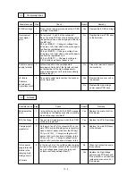
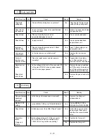
Failure in static-
charge eliminator
Is there any dirt on the static-charge eliminator?
Clean the static-charge
eliminator.
I-5
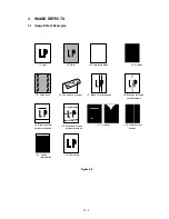
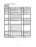
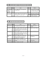
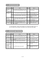
Polka dots
Possible cause
Step
Check
Result
Remedy
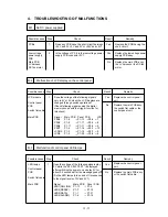
Dirt on the
transfer roller
2
Is there continuity between the static-charge
eliminator and the chassis?
Yes
Ensure the grounding of the
static-charge eliminator.
Static-charge
eliminator
grounding failure
3
Does print quality improve when the transfer
roller is replaced?
Yes
Clean the transfer roller [Use dry
lint-free paper (producing little
paper dust) to clean the transfer
roller. Never use solvents] and,
if the dirt remains, replace the
transfer roller assy.
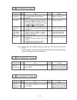
1
Yes
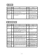
Dirt on the
PF guide
Is there any dirt on the back of the paper feed
guide and the jam remove cover near the static-
charge eliminator?
Clean the PF guide or the
jam remove cover.
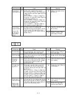
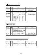
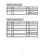
I-6
Dirt on back of paper
Possible cause
Step
Check
Result
Remedy
Dirt on the
transfer roller
2
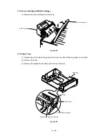
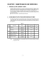
Open the toner cartridge lid in the printer, pull
out the EP-ED cartridge and remove the paper
in the printer. Is there already dirt on the back
of the sheet thus removed?
No
Go to Step 6.
-
3
Is there any dirt on the transfer roller?
Yes
Clean the transfer roller and,
if the dirt remains, replace
the transfer roller assy.
Transfer input
signal error
4
Does the voltage at the 6 pin (HVT1) of the
connector P6 on the main PCB change from
9V to 0V for about 0.8 seconds?
Yes
Replace the main PCB assy
or the harness.
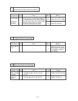
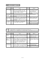
5
No
Dirt on power
supply terminal
Clean the transfer roller right end bearing, the
check continuity between the transfer roller
power supply spring and the terminal of the
high-voltage transfer unit. Is there continuity?
Clean the contact to assure
the continuity.
Failure in the
transfer high-
voltage circuit
Replace the high-voltage
power supply PCB assy.
No
Dirt the fixing
guide
Is there any dirt on the fixing unit inlet guide?
6
Clean the fixing unit inlet
guide.
Yes
Fixing roller
grounding failure
Are the upper and lower rollers of the fixing
unit securely connected to the chassis via the
diode?
7
Ensure the grounding.
No
Replace the fixing unit.
Yes
Fixing unit failure
Содержание HL-1260
Страница 1: ...SERVICE MANUAL MODEL HL 1260 R LASER PRINTER ...
Страница 40: ...III 8 K D E F A C 2 C 3 C C 1 J B G 2 G 1 G H I Figure 3 6 Main PCB Circuit ...
Страница 108: ...Appendix 2 Paper Feed Size SW PCB Circuitry Diagram 1 1 A 2 CODE NAME UK2516000 B48K139 140CIR JW 27 95 P053 ...
Страница 109: ...Appendix 3 Main PCB Circuitry Diagram 1 8 A 3 CODE NAME UK2495000 B48K158 159CIR 1 8 ...
Страница 110: ...Appendix 4 Main PCB Circuitry Diagram 2 8 A 4 CODE NAME UK2495000 B48K158 159CIR 2 8 ...
Страница 111: ...Appendix 5 Main PCB Circuitry Diagram 3 8 A 5 CODE NAME UK2495000 B48K158 159CIR 3 8 ...
Страница 112: ...Appendix 6 Main PCB Circuitry Diagram 4 8 A 6 CODE NAME UK2495000 B48K158 159CIR 4 8 ...
Страница 113: ...Appendix 7 Main PCB Circuitry Diagram 5 8 A 7 CODE NAME UK2495000 B48K158 159CIR 5 8 ...
Страница 114: ...Appendix 8 Main PCB Circuitry Diagram 6 8 A 8 CODE NAME UK2495000 B48K158 159CIR 6 8 ...
Страница 115: ...Appendix 9 Main PCB Circuitry Diagram 7 8 A 9 CODE NAME UK2495000 B48K158 159CIR 7 8 ...
Страница 116: ...Appendix 10 Main PCB Circuitry Diagram 8 8 A 10 CODE NAME UK2495000 B48K158 159CIR 8 8 ...
Страница 117: ...Appendix 11 Control Panel PCB Circuitry Diagram 1 1 A 11 CODE NAME UK2527000 B48K143CIR ...
Страница 118: ...Appendix 12 Scanner LD PCB Circuitry Diagram 1 1 A 12 CODE NAME UK2674000 B48K165CIR ...
Страница 119: ...SERVICE MANUAL MODEL HL 1260e 1660 R LASER PRINTER ...
Страница 144: ...III 7 Figure 3 6 Main PCB Circuit A C 2 C 3 C J K B I H 1 H 2 C 1 H G G 1 G 2 F E D ...
Страница 168: ...CODE UK3268000 B48K259 235CIR 1 7 NAME Appendix 3 Main PCB Circuitry Diagram 1 7 ...
Страница 169: ...CODE UK3268000 B48K259 235CIR 2 7 NAME Appendix 4 Main PCB Circuitry Diagram 2 7 A 3 ...
Страница 170: ...CODE UK3268000 B48K259 235CIR 3 7 NAME Appendix 5 Main PCB Circuitry Diagram 3 7 A 4 ...
Страница 171: ...CODE UK3268000 B48K259 235CIR 4 7 NAME Appendix 6 Main PCB Circuitry Diagram 4 7 A 5 ...
Страница 172: ...CODE UK3268000 B48K259 235CIR 5 7 NAME A 6 Appendix 7 Main PCB Circuitry Diagram 5 7 ...
Страница 173: ...CODE UK3268000 B48K259 235CIR 6 7 NAME Appendix 8 Main PCB Circuitry Diagram 6 7 A 7 ...
Страница 174: ...CODE UK3268000 B48K259 235CIR 7 7 NAME Appendix 9 Main PCB Circuitry Diagram 7 7 A 8 ...
Страница 175: ...CODE UK3253000 B48K253CIR 1 1 NAME Appendix 11 Scanner LD PCB Circuitry Diagram 1 1 A 9 ...
Страница 188: ...PARTS REFERENCE LIST MODEL HL 1260e R LASER PRINTER ...
Страница 213: ...I Brother Laser Printer HL 1260e HL 1660 USER S GUIDE ...
Страница 421: ...APPENDICES Appendix 15 HP LaserJet 4 Mode Roman 8 8U ISO Latin1 0N ISO Latin2 2N ISO Latin5 5N ...
Страница 422: ...USER S GUIDE Appendix 16 PC 8 10U PC 8 D N 11U PC 850 12U PC 852 17U ...
Страница 423: ...APPENDICES Appendix 17 PC 8 Turkish 9T Windows Latin1 19U Windows Latin2 9E Windows Latin5 5T ...
Страница 424: ...USER S GUIDE Appendix 18 Legal 1U Ventura Math 6M Ventura Intl 13J Ventura US 14J ...
Страница 425: ...APPENDICES Appendix 19 PS Math 5M PS Text 10J Math 8 8M Pi Font 15U ...
Страница 426: ...USER S GUIDE Appendix 20 MS Publishing 6J Windows 3 0 9U Desktop 7J MC Text 12J ...
Страница 429: ...APPENDICES Appendix 23 PC 8 PC 8 D N PC 850 PC 852 ...
Страница 430: ...USER S GUIDE Appendix 24 PC 860 PC 863 PC 865 PC 8 Turkish ...
Страница 431: ...APPENDICES Appendix 25 IBM Mode PC 8 PC 8 D N PC 850 PC 852 ...
Страница 432: ...USER S GUIDE Appendix 26 PC 860 PC 863 PC 865 PC 8 Turkish ...
Страница 433: ...APPENDICES Appendix 27 HP GL Mode ANSI ASCII 9825 CHR SET ...
Страница 434: ...USER S GUIDE Appendix 28 FRENCH GERMAN SCANDINAVIAN SPANISH LATIN JIS ASCII ...
Страница 435: ...APPENDICES Appendix 29 ROMAN8 EXT ISO IRV ISO SWEDISH ISO SWEDISH N ...
Страница 436: ...USER S GUIDE Appendix 30 ISO NORWAY 1 ISO GERMAN ISO FRENCH ISO U K ...
Страница 437: ...APPENDICES Appendix 31 ISO ITALIAN ISO SPANISH ISO PORTUGUESE ISO NORWAY 2 ...


