


38
10.7
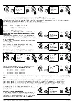
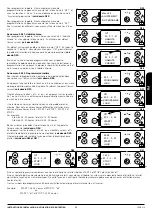
THERMAL ALARM
If during the working phase the thermal security alarm shows up
(
see drawing D72
), the turn-off stage will be immediately activated.
This alarm means an overheating of the internal part of the tank; this
device blocks the operation of the machine. The restart needs to be
done manually by an authorised technician.
The restoration of the 90ºC safety device is not included in the
warranty unless the technical assistance centre demonstrates a
faulty component.
10.8
COMBUSTION CHAMBER PRESSURE ALARM
It happens when there is a pressure change in the combustion
chamber (door open, dirt registers, air returns...). The electronic
pressostat blocks the working of the stove and shows the alarm.
After that the turn-off stage will be immediately activated (
see
drawing D73
).
10.9
LACK OF PRIMARY AIR INTAKE FLOW ALARM
Your stove has a flow sensor placed inside the primary air suction
pipe. It detects the proper circulation of combustion air and the
smoke exhaust. In case of insufficient air inlet (due to incorrect
smoke outlet or improper air intake), the sensor sends a “block”
signal. After that the turn-off stage will be immediately activated (
see
drawing D74
).
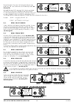
10.10
AUGER FAILURE ALARM
The control of the fuel amount to the stove is automatically made
through the electronic programming. It goes off in the event of the
endless breakdown. If this happens, the stove stops and the display
will show up the following alarm. Right after, the turn-off stage will be
immediately activated (
see drawing D75
).
If this alarm appears you must contact the technical support service.
10.11
FLOW SENSOR ANOMALY ALARM
In case of anomaly of the flow sensor, placed on the primary air
aspiration tube, a blockage signal is send to the stove and right after
the turn-off stage will be immediately activated. (
See drawing D76
).
If this alarm appears you must contact the technical support service.
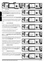
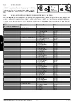
10.12
ALARM LIST, PROBLEM AND POSSIBLE SOLUTIONS
Alarm
Code
Description
Problem
Possible solution
AL1
BLACK OUT
The stove has been temporarily
without electric current.
Press button 4 for a few seconds and let the final cleaning
stage to finish. The boiler will come back to the turn-off status.
AL 2
SMOKE PROBE
Problem with the smoke probe.
Check the probe connection or replace it.
AL 3
TEMP. SMOKE
The smoke temperature is higher
than 270ºC.
Regulate the pellet drop and/or the extractor speed. Verify the
type of fuel that has been used.
AL 4
BREAKDOWN
EXTRACTOR
Problem with the smoke
extractor.
Check the extractor electrical connection or replace it.
AL 5
START-UP FAILURE
The fuel does not fall or burn.
Check the geared motor and the resistor way of working.
Check a possible blockage of the endless. Verify that there is
fuel in the tank.
AL 6
NO PELLET
There is no fuel in the hopper or
it does not fall inside the burner.
Refill tank. Check the endless working. Check the fuel
characteristics and that it has not become compacted. Clean
the bottom of the hopper.
AL 7
THERMAL ALARM
The fuel thermal security
thermostat has shot up.
Restart the thermostat manually. Check the reason why the
temperature is excessive and provoked the overheating (fuel
drop, draw excess, fuel type...)
AL 8
DEPRESSION
The combustion chamber is on
depression.
Verify that the chamber is hermetic: check locks, gaskets…
etc. Check that the gas installation is correct (excess of
horizontal sections, elbow joint, etc). Possible fuel blockage.
AL 9
LACK OF FLOW
Lack of primary air or installation
not appropriate.
Check the primary air inlet. Verify installation (excess of
horizontal section, curves, dirtiness, etc).
AL
FLOWMETER FAILURE
The flow sensor is broken.
Replace the flow sensor.
AL b
AUGER ERROR
The auger spins continuously.
Verify the electrical connection of the endless.
D72
ALARM 7
SECURITY
THERMAL
D73
ALARM 8
PRESSURE
FAILURE
D74
ALARM 9
FLOW
ALARM
D75
ALARM b
AUGER
ERROR
D76
ALARM
FLOWMETER
FAILURE
INSTALLATION, OPERATING AND SERVICING INSTRUCTIONS
AIR SERIES
EN
Содержание Air Series
Страница 101: ...100 11 1 ALBA 1 27 12 25 4 6 8 2 3 5 7 9 10 11 13 14 15 19 20 21 22 23 24 26 32 33 34 17 16 28 29 30 31 FT ...
Страница 103: ...102 11 2 KIRA 1 27 12 25 4 6 8 2 3 5 7 9 10 11 13 14 15 16 17 18 19 20 21 22 23 24 26 28 29 30 31 32 33 FT ...
Страница 105: ...104 11 3 NINA FT ...
Страница 117: ...116 11 9 LOLA 15 21 20 17 14 13 11 23 12 19 22 18 16 8 9 7 26 28 27 25 24 5 10 6 3 4 1 2 37 36 35 34 33 32 29 31 30 FT ...
Страница 121: ...120 11 11 SARA NC ...
Страница 123: ...122 11 12 EVA FT ...
Страница 125: ...124 11 13 EVA NC FT ...
Страница 127: ...126 11 14 CORAL FT ...