background image

Removing an interface module

To remove an interface module, first perform the steps in section 

Before removing an interface module

 on page 128, then complete the

following steps.

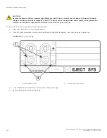
1. Put on the ESD wrist strap and ground yourself by inserting the plug into the ESD connector located in the lower right corner of

the chassis front.

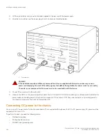
2. Use the #2 Phillips-head or flathead screwdriver to loosen the two screws on the ends of the module.
3. Pull the card ejectors towards you, and away from the module front panel. This action unseats the module from the backplane.
4. Pull the module out of the chassis, and place in an anti-static bag for storage if desired.
5. If you plan to replace the removed module with a different type of module, you must first remove the module configuration. To

do so, enter the 

no module 

slotnum

 command at the global CONFIG level of the CLI, then save the configuration to flash

memory. For example,

device(config)# no module 4

device(config)# exit

device# write mem

NOTE

If you attempt to insert a module of a different type without first removing the previous module configuration, the
system will display an error message.

6. Install a new module in the slot. For information about performing this task, refer to 

Installing a new interface module

 on page

129.

CAUTION
If you do not install a module or a power supply in a slot, you must keep the slot filler panel in place. If you run the
chassis with an uncovered slot, the system will overheat.

Installing a new interface module

You can install an interface module in the FSX 800 and FSX 1600 chassis while the chassis is powered on and running.

NOTE

Interface modules are interchangeable among all FastIron X Series devices. However, if you install them in a Brocade device
other than a FastIron X Series device, the device and interface modules will not function properly.

DANGER

For safety reasons, the ESD wrist strap should contain a series 1 megaohm resistor.

A #2 Phillips-head or flathead screwdriver.

To install a new interface module in the chassis, perform the following tasks.

1. Follow the preparation procedure in the section 

Before removing an interface module

 on page 128.

2. Put on the ESD wrist strap and ground yourself by inserting the plug into the ESD connector located in the lower right corner of

the chassis front.

3. Remove the module from its packaging.
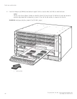
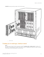
4. Insert the module into the chassis slot as shown in the figures below, and slide the card along the card guide until the ejectors

on either side of the module move close to the module front panel.

5. Push the ejectors in toward the center of the module. This action will fully seat the module in the backplane.

Replacing an interface module

Brocade FastIron SX Series Chassis Hardware Installation Guide

Part Number: 53-1003613-04

129

Содержание FastIron SX

Страница 1: ...HARDWARE INSTALLATION GUIDE Brocade FastIron SX Series Chassis Hardware Installation Guide Part Number 53 1003613 04 Publication Date 15 June 2017 ...

Страница 2: ...ribes features that may not be currently available Contact a Brocade sales office for information on feature and product availability Export of technical data contained in this document may require an export license from the United States government The authors and Brocade Communications Systems Inc assume no liability or responsibility to any person or entity with respect to the accuracy of this ...

Страница 3: ...interfaces 34 Power supplies 35 Cooling system 43 Built in mounting brackets 44 FSX 1600 slot identification 44 Installing FastIron SX Devices 47 Unpacking the system 47 Installation precautions 48 General precautions 48 Lifting precautions 48 Power precautions and warnings 48 Preparing the installation site 50 Cabling infrastructure 50 Installation location 50 Removing extra shipment screws FSX 8...

Страница 4: ...ons 93 Support for digital optical monitoring 94 Managing the Chassis and Modules 95 Overview 95 Displaying chassis status and temperature readings 95 Managing the cooling system 99 Configuring the cooling system 99 Monitoring the cooling system 103 Displaying the Syslog configuration and static and dynamic buffers 105 Static and dynamic buffers 106 Syslog messages for PCI hardware errors 106 Mana...

Страница 5: ...ling an interface module 131 Replacing a copper or fiber optic module 132 Removing a copper or fiber optic module 132 Installing a new copper or fiber optic module 133 Cabling a fiber optic module 134 Installing or replacing a power supply 134 Determining which power supply failed 134 Removing an AC power supply 135 Removing a DC power supply 137 Installing a new power supply 139 Connecting AC pow...

Страница 6: ...ecifications 167 Regulatory Statements 169 CE Statement 169 China ROHS 169 BSMI statement Taiwan 169 Canadian requirements 170 China CC statement 170 Europe and Australia CISPR 22 Class A Warning 171 FCC warning US only 171 Germany 171 KCC statement Republic of Korea 171 VCCI statement 171 Caution and Danger Notices 173 Cautions 173 General cautions 173 Electrical cautions 174 Danger Notices 178 G...

Страница 7: ...r the device might reboot CAUTION A Caution statement alerts you to situations that can be potentially hazardous to you or cause damage to hardware firmware software or data DANGER A Danger statement indicates conditions or situations that can be potentially lethal or extremely hazardous to you Safety labels are also attached directly to products to warn of these conditions or situations Text form...

Страница 8: ...it the Brocade website to locate related documentation for your product and additional Brocade resources White papers data sheets and the most recent versions of Brocade software and hardware manuals are available at www brocade com Product documentation for all supported releases is available to registered users at MyBrocade Click the Support tab and select Document Library to access product docu...

Страница 9: ... issues Continental US 1 800 752 8061 Europe Middle East Africa and Asia Pacific 800 AT FIBREE 800 28 34 27 33 Toll free numbers are available in many countries For areas unable to access a toll free number 1 408 333 6061 Brocade OEM customers If you have purchased Brocade product support from a Brocade OEM solution provider contact your OEM solution provider for all of your product support needs ...

Страница 10: ...Brocade FastIron SX Series Chassis Hardware Installation Guide 10 Part Number 53 1003613 04 ...

Страница 11: ...information about the features supported on a hardware platform refer to the appropriate Features and Standards Support Matrix document What s new in this document There are no enhancements in this edition Brocade FastIron SX Series Chassis Hardware Installation Guide Part Number 53 1003613 04 11 ...

Страница 12: ...Brocade FastIron SX Series Chassis Hardware Installation Guide 12 Part Number 53 1003613 04 ...

Страница 13: ...evices However you cannot mix Second Generation and Third Generation modules in the same device The FSX 800 and FSX 1600 management switch fabric and interface modules are hot swappable which means you can remove and replace them while the device is powered on and running All FastIron X Series chassis devices have a passive backplane FastIron X Series chassis devices have completely separate data ...

Страница 14: ...erged services such as Voice over IP VoIP WLAN access points IP surveillance cameras and other IP technology devices PoE technology eliminates the need for an electrical outlet and dedicated UPS near IP powered devices With power sourcing devices such as Brocade s FastIron X Series chassis devices with PoE and PoE power is consolidated and centralized in the wiring closets improving the reliabilit...

Страница 15: ...ck unit RU to the height of the chassis FIGURE 1 FSX 800 chassis and component slots The FSX 800 chassis ships from the factory with the following components installed Two switch fabric modules A slot panel in each empty interface module slot and power supply slot The slot panels ensure proper airflow within the chassis One AC power supply A fan tray assembly which contains the cooling system for ...

Страница 16: ...filler panel in place If you run the chassis with an uncovered slot the system will overheat The figure below shows the FSX 800 slots where you install modules and power supplies and the electrostatic discharge ESD connector into which you can plug an ESD wrist strap to ground yourself while handling and installing modules FIGURE 2 FSX 800 module slots 1 Slot 1 2 Slot 2 3 Slot 3 4 Slot 4 5 Slot 5 ...

Страница 17: ...units in height and contains the following component slots Two half slots for management modules Two half slots for switch fabric modules Sixteen half slots for interface modules Eight slots for power supplies along the bottom of the card shelf The following figure shows the front of the FSX 1600 device Hardware components Brocade FastIron SX Series Chassis Hardware Installation Guide Part Number ...

Страница 18: ...FIGURE 3 FSX 1600 device Hardware components Brocade FastIron SX Series Chassis Hardware Installation Guide 18 Part Number 53 1003613 04 ...

Страница 19: ... power supplies Before installing any modules or power supplies you must remove the slot panel CAUTION If you do not install a module or a power supply in a slot you must keep the slot filler panel in place If you run the chassis with an uncovered slot the system will overheat FSX 1600 slot identification The following figure identifies the slots where you can install modules and power supplies as...

Страница 20: ...nterface slot 14 15 Interface slot 15 16 Interface slot 16 17 Management slot 17 18 Management slot 18 19 Switch fabric slot 1 20 Switch fabric slot 2 21 ESD ground connector Management modules Each FSX 800 and FSX 1600 device requires one management module and as an option supports two management modules for full redundancy Each management module occupies one half slot Hardware components Brocade...

Страница 21: ...ABLE 2 Information about FSX 800 and FSX 1600 management modules Part Number Description Microprocessor Speed MHz MB SDRAM XL management modules SX FI ZMR XL no ports 1500 quad core 4096 SX FI ZMR XL PREM6 SX FI 2XGMR XL 2 ports SX FI 2XGMR XL PREM NOTE XL management modules ending with PREM6 support full Layer 3 IPv4 and IPv6 routing protocols FSX 800 and FSX 1600 management modules perform the f...

Страница 22: ... the FSX 800 and FSX 1600 management modules The 10 100 1000 RJ45 copper port on the management module enables you to attach a PC or terminal and access the system CLI directly or through a Telnet connection LEDs on the FSX 800 and FSX 1600 management modules The management modules provide status information through the LEDs listed in the table below TABLE 3 FSX 800 and FSX 1600 management module ...

Страница 23: ... management modules has an RJ45 connector The Console port interfaces with the control plane only and does not interface with the data plane Reset button The SX FI ZMR XL and SX FI ZMR XL PREM6 management modules and the SX FI 2XGMR XL and SX FI 2XGMR XL PREM management modules do not have a reset button Specifying a port address You can specify a port address for a data port or a management port ...

Страница 24: ...perly Interface modules This section describes interface modules for the FastIron X Series chassis devices The following installation rules apply In the FSX 800 device you can install up to eight single slot and four double interface modules in the slots shown in FSX 800 chassis on page 15 In the FSX 1600 device you can install up to 16 single slot and eight double slot interface modules in the sl...

Страница 25: ... line module while hot swap of a line module is taking place Wait until the current hot swap of the line module is completed The following message indicates that the hot swap insertion of a module is completed Module 1 is up and running The following console message indicates that the hot swap removal of a module is completed Powering off the module in slot 1 NOTE It is recommended that modules be...

Страница 26: ...to physical ports carrying traffic to the backplane of the device The FastIron supports 2 1 oversubscription allowing two devices to pass traffic through a single internal physical port to take advantage of bandwidth which might otherwise go unused Oversubscription is achieved on the SX FI48GPP by connecting 48 external ports to 24 internal physical ports providing 2 1 oversubscription No CLI comm...

Страница 27: ...slot spaces and can be installed in certain slots only For details refer to Installing management and interface modules on page 55 48 port 10 100 1000 Mbps Ethernet PoE interface module limitations The following limitations apply to this module Q in Q and SAV VLAN stacking are not supported on this module Second Generation 24 port Gigabit Ethernet copper interface module The Second Generation 24 p...

Страница 28: ...4 LEDs for PoE status NOTE The PoE LEDs work only when PoE is enabled on your device LEDs for 24 port copper module The front panel of the 24 port Gigabit Ethernet copper module includes 24 LEDs top that indicate the status of each port and 24 LEDs bottom that indicate the PoE status NOTE The PoE LEDs work only when PoE is enabled on your device Hardware components Brocade FastIron SX Series Chass...

Страница 29: ...enabled a power consuming device has been detected and the module is supplying power to the device Off The port is not providing in line power Third Generation 24 port Gigabit Ethernet copper module with PoE The 24 port Gigabit Ethernet copper interface module with PoE supports both IPv4 and IPv6 The figure below shows the front panel of the IPv4 and IPv6 24 port Gigabit Ethernet copper interface ...

Страница 30: ...E if applicable Round LED located beneath the ports The first left most LED is for port 1 the second LED is for port 2 the third LED is for port 3 etc On Green The port is enabled a power consuming device has been detected and the module is supplying power to the device Off The port is not providing in line power 24 port 100 1000 hybrid fiber interface module The 100 1000 hybrid fiber module has 2...

Страница 31: ... in Network interfaces on page 34 Support for 100Base FX on the 100 1000 interface module The 24 port 100 1000 fiber interface module supports the following types of SFPs for 100Base FX Multimode SFP maximum distance is 2 kilometers Bidirectional single mode SFP maximum distance is 10 kilometers Long Reach LR maximum distance is 40 kilometers Intermediate Reach IR maximum distance is 15 kilometers...

Страница 32: ...opper 10GBase SR 10GBase LR and 10GBase ER fiber optic cabling for LAN FIGURE 12 Second Generation 2 port 10 Gigabit Ethernet interface module front panel FIGURE 13 Third Generation 2 port 10 Gigabit Ethernet interface module front panel LEDs for Second Generation 2 port 10 Gigabit Ethernet module The 10 Gbps ports provide status information using the LEDs listed below TABLE 9 LEDs for 10 Gbps por...

Страница 33: ...s to physical ports carry traffic to the backplane of the device An oversubscribed module allows aggregate bandwidth of user ports exceed the bandwidth of the Network Processor NP The SX FI 8XG has two separate NPs The front end NP provides basic traffic classification and is used as a traffic multiplexer The back end NP is a traffic aggregator and handles data forwarding The SX FI 8XG module has ...

Страница 34: ...ons on page 167 The output of the show media command displays the type of media installed in the ports TABLE 12 Network interfaces Interface Show Media Description 1000Base BX D M GBXD 1000Base BX U M GBXU 1000Base CWDM Cxxxx xxx denotes wavelength for example C1550 1000Base LHA M LHA 1000Base LHB M LHB 1000Base LX M LX 1000Base SX M SX 1000Base SX2 M XR or M SX2 1000Base T M C 100Base BX M FBXD o...

Страница 35: ...ort region 1 8 port 10 Gigabit Ethernet interface module two port regions Ports 1 4 belong to port region 0 Ports 5 8 belong to port region 1 Layer 3 routing protocol table sizes Use the show default values command to display Layer 3 routing protocol table sizes The command output shows the default maximum and currently configured values Refer to the FastIron Ethernet Switch Layer 3 Configuration ...

Страница 36: ...X Series chassis devices Non PoE devices The 12 volt AC and DC power supplies also called system SYS power supplies provide power to one management module and up to eight non PoE interface modules In the FSX 800 you can install a second 12 volt power supply for redundancy The FSX 1600 comes with and requires two 12 volt power supplies and supports up to four 12 volt power supplies for redundancy P...

Страница 37: ...suming devices are attached In the FSX 800 you can install a second 12 volt power supply for redundancy The FSX 1600 comes with and requires two 12 volt power supplies and supports up to four 12 volt power supplies for redundancy The 52 54 volt PoE power supplies provide power to the PoE daughter card and ultimately to PoE power consuming devices The number of PoE power consuming devices that one ...

Страница 38: ...Series POE will cause extensive damage to your equipment All power supplies are auto sensing and auto switching Power supplies are installed in the slots along the bottom of the device In FSX 800 devices the 12 volt system power supplies occupy slot numbers 3 and 4 on the right with the redundant supply in slot 4 PoE power supplies occupy slot numbers 1 and 2 on the left FIGURE 15 Power supply pla...

Страница 39: ... before you install it in or remove it from the device Otherwise the power supply or the device could be damaged as a result The device can be running while a power supply is being installed or removed but the power supply itself should not be connected to a power source Replacement power supplies Replacement power supplies for the SX ACPWR SYS and SX ACPWR PoE are functionally equivalent to the o...

Страница 40: ...er supplies The latching mechanism protrudes slightly in front making the power supplies slightly longer in depth Although the model numbers SX ACPWR SYS and SX ACPWR PoE for the replacement and original power supplies are identical the manufacturing part numbers are different The manufacturing part numbers are inscribed on the labels affixed to the top of the power supplies In addition the manufa...

Страница 41: ...as power DC IN DC supply only Green steady The power supply is receiving DC power from a DC power source OFF The power supply is not receiving power from a DC power source You can do the following Make sure that the power supply cables are connected securely to the power source and the power supply Make sure that the DC power source is 48VDC 37 0 A Make sure that the power source has power DC OUT ...

Страница 42: ...lly to generate more power than they are capable of The system will react to a drop in voltage by increasing the current draw The hardware will shut down due to over current protection or under voltage protection whichever takes place first One by one the interface modules will shut down until the power is within the power budget of the remaining power supplies There is no particular order in whic...

Страница 43: ...r supply use the calculation One power supply 1080W over power consumed by PoE port 30W 1080W 30W 36 ports The table below shows the maximum PoE port density for the FI SX 24 GPP and FI SX48GPP interface modules TABLE 16 Maximum number of PoE class 30W ports per power supply Power Supply Number of Power Supplies FSX 800 FSX 1600 SX ACPWR PoE and SX DCPWR PoE 1 36 36 SX ACPWR PoE and SX DCPWR PoE 2...

Страница 44: ...temperature exceeds the highest threshold You can change default low and high temperature thresholds for modules and fan speeds For more information refer to Changing temperature thresholds for thermal planes and fan speeds on page 100 The device ships with all fan components fully installed in the fan tray For information about replacing the fan tray refer to one of the following sections Replaci...

Страница 45: ... Interface slot 7 8 Interface slot 8 9 Interface slot 9 10 Interface slot 10 11 Interface slot 11 12 Interface slot 12 13 Interface slot 13 14 Interface slot 14 15 Interface slot 15 16 Interface slot 16 17 Management slot 17 18 Management slot 18 19 Switch fabric slot 1 20 Switch fabric slot 2 21 ESD ground connector Hardware components Brocade FastIron SX Series Chassis Hardware Installation Guid...

Страница 46: ...Brocade FastIron SX Series Chassis Hardware Installation Guide 46 Part Number 53 1003613 04 ...

Страница 47: ...the following items Review this list and verify the contents NOTE If any items are missing contact the place of purchase FastIron SX chassis with the following components installed One or two 12 volt power supplies Fan tray assembly or assemblies Slot panels installed in all unoccupied slots Two switch fabric modules installed Rack Mount Kit FSX 1600 models only Management module or modules packag...

Страница 48: ... Place the heaviest device at the bottom and progressively place lighter devices above Power precautions and warnings NOTE The power supplies are hot swappable which means they can be removed and replaced while the chassis is powered on and running CAUTION Remove the power cord from a power supply before you install it in or remove it from the device Otherwise the power supply or the device could ...

Страница 49: ... is located on the side of the chassis adjacent ground symbol CAUTION For the DC input circuit to the system make sure there is a 30 amp circuit breaker minimum 48VDC double pole on the input to the terminal block The input wiring for connection to the product should be copper wire 8 AWG marked VW 1 and rated a minimum of 90 degrees celsius CAUTION All devices with AC power sources are intended fo...

Страница 50: ...n mechanical damage to the power supply and power supply slot DANGER High Touch Current Earth connection essential before connecting supply Preparing the installation site Cabling infrastructure NOTE Ensure that the proper cabling is installed in the site For information on cabling refer to the following sections in this guide Attaching a management station on page 62 Connecting network devices on...

Страница 51: ...ts on the FSX 1600 chassis task Before performing this task you should have an assembled rack and a 2 Phillips head screwdriver Keep the following in mind when mounting a chassis in a rack DANGER Make sure the rack housing the device is adequately secured to prevent it from becoming unstable or falling over DANGER Mount the devices you install in a rack as low as possible Place the heaviest device...

Страница 52: ... on the brackets Do not secure the screws completely leave approximately 1 4 inch of clearance between the back of the screw head and the rack FIGURE 22 Positioning two or four mounting screws in a rack 1 Keyhole slots Installing the chassis in a rack Brocade FastIron SX Series Chassis Hardware Installation Guide 52 Part Number 53 1003613 04 ...

Страница 53: ...nto the rack 6 Tighten all screws to secure the chassis in place 7 Repeat Step 2 through Step 6 to mount each subsequent chassis in the same rack Installing mounting brackets on the FSX 1600 chassis The FSX 1600 chassis does not ship with mounting brackets installed You will need to install the brackets using a 2 Phillips or flathead screwdriver Mount the brackets as shown in the figure below Sinc...

Страница 54: ...1600 chassis Repeat Step 2 through Step 6 of the Installing the chassis in a rack task to install the FSX 1600 chassis in the rack Installing the chassis in a rack Brocade FastIron SX Series Chassis Hardware Installation Guide 54 Part Number 53 1003613 04 ...

Страница 55: ... can remove and insert them while the chassis is powered on and running NOTE Management modules are dedicated which means you must install them in the appropriate device You cannot mix Second Generation and Third Generation 3 modules together in the same chassis Because 48 port 10 100 1000 Mbps Ethernet POE interface modules SX FI48GPP occupy two vertical half slots in the FastIron SX 800 or 1600 ...

Страница 56: ... NOTE You can install management modules in the FSX 800 and FSX 1600 chassis while it is powered on and running 1 Put on the ESD wrist strap and ground yourself by inserting the plug into the ESD connector located on the chassis front panel 2 Remove the module from the packaging 3 Insert the management module or interface module into the appropriate slot and slide the card along the card guide unt...

Страница 57: ... The following illustrations show placement of management and interface modules in a FastIron X Series device FIGURE 25 Installing a management module in the FSX 800 chassis Installing management and interface modules Brocade FastIron SX Series Chassis Hardware Installation Guide Part Number 53 1003613 04 57 ...

Страница 58: ...FIGURE 26 Installing a management module in the FSX 1600 chassis Installing management and interface modules Brocade FastIron SX Series Chassis Hardware Installation Guide 58 Part Number 53 1003613 04 ...

Страница 59: ...FIGURE 27 Installing an interface module in the FSX 800 chassis Installing management and interface modules Brocade FastIron SX Series Chassis Hardware Installation Guide Part Number 53 1003613 04 59 ...

Страница 60: ...FIGURE 28 Installing an interface module in the FSX 1600 chassis Installing management and interface modules Brocade FastIron SX Series Chassis Hardware Installation Guide 60 Part Number 53 1003613 04 ...

Страница 61: ...E 29 Installing an SX FI48GPP POE interface module in an FSX 800 device Installing management and interface modules Brocade FastIron SX Series Chassis Hardware Installation Guide Part Number 53 1003613 04 61 ...

Страница 62: ...t the FastIron X Series switch to your existing management network and manage the switch along with other network devices from a management station To do this you can connect a switch to a Gigabit Ethernet port on the management module Refer to Attaching a switch to an Ethernet port on page 63 NOTE The management network into which you can connect a Gigabit Ethernet port must be separate and isola...

Страница 63: ...he appropriate cable 2 Open the terminal emulation program and set the session parameters as follows Baud 9600 bps Parity None Data bits 8 Stop bits 1 Flow control None Attaching a switch to an Ethernet port The 10 100 1000 Ethernet copper ports on the FSX 800 and FSX 1600 management module and the combination Gigabit Ethernet copper and fiber ports on the FSX management module allow you to attach...

Страница 64: ...ingdom and European compatible power cords are also available Input connector and plug In AC deployments the power cords plug into the rear of the chassis using C20 inputs The AC power supplies are installed in the front of the chassis and receive power from the inputs on the back In DC deployments a two position terminal block is located on the power supply itself and DC power is wired on the fro...

Страница 65: ...shows the power plug for the SX ACPWR2500 POE power supply FIGURE 32 AC power cable plug for SX ACPWR2500 POE power supply The figure below shows the DC connector for the SX DCPWR SYS and SX DCPWR POE power supplies Powering on the system Brocade FastIron SX Series Chassis Hardware Installation Guide Part Number 53 1003613 04 65 ...

Страница 66: ...ve Terminal Screw 4 Negative Terminal Screw 5 AWG Wire 6 Terminal Screw Cover Power source interruptions The table below shows how the FastIron chassis protects against power surges and power drops Powering on the system Brocade FastIron SX Series Chassis Hardware Installation Guide 66 Part Number 53 1003613 04 ...

Страница 67: ... chassis AC power is supplied though an AC power cord that is connected to the back of the chassis Perform the following tasks to connect AC power to the chassis 1 At the rear of the chassis locate the power receptacles on the power supplies 2 Lift the cord retainer and connect a Brocade supplied AC power cord to the power supply Powering on the system Brocade FastIron SX Series Chassis Hardware I...

Страница 68: ...er the power plug to hold it in place FIGURE 34 Connecting the AC power cord on an FSX 800 device 1 Cord retainer Powering on the system Brocade FastIron SX Series Chassis Hardware Installation Guide 68 Part Number 53 1003613 04 ...

Страница 69: ...FIGURE 35 Connecting the AC power cord on an FSX 1600 device Powering on the system Brocade FastIron SX Series Chassis Hardware Installation Guide Part Number 53 1003613 04 69 ...

Страница 70: ...OK LEDs should be green steady which indicates the power supply is providing power to the components If it is amber or OFF the power supply is not providing power to the components The ALM LED should be OFF Connecting DC power to the chassis You can use a DC power source for the Brocade chassis using a DC to DC power supply DC power must be supplied at 48 V and 30 A To perform this task you need t...

Страница 71: ...t to the ground position on the chassis The ground position is located on the side or rear of the chassis next to the ground symbol FIGURE 36 Chassis ground on FXS 800 device 1 Ground Powering on the system Brocade FastIron SX Series Chassis Hardware Installation Guide Part Number 53 1003613 04 71 ...

Страница 72: ...gs FIGURE 37 Power lugs and cover screws 1 Screws holding power lugs 2 Screws holding transparent cover 3 Use a Phillips head screwdriver to remove the power lugs Refer to the second figure below Powering on the system Brocade FastIron SX Series Chassis Hardware Installation Guide 72 Part Number 53 1003613 04 ...

Страница 73: ... to the two figures below FIGURE 38 Power supply wire 1 8 AWG power supply wire This equipment installation must meet NEC CEC code requirements Consult local authorities for regulations Powering on the system Brocade FastIron SX Series Chassis Hardware Installation Guide Part Number 53 1003613 04 73 ...

Страница 74: ... as marked on the power supply 7 Observe the LEDs on the power supply front panel The DC IN and DC OUT LEDs should be green steady which indicates the power supply is providing power to the components If it is amber or OFF the power supply is not providing power to the components The ALM LED should be OFF Powering on the system Brocade FastIron SX Series Chassis Hardware Installation Guide 74 Part...

Страница 75: ...ule or is managing the switch fabric and interface modules A problem may have occurred during initialization Check your PC or terminal for possible error messages Pwr On The module is receiving power Off The module is not receiving power You can do the following Make certain that the module is installed properly For more information refer to Installing management and interface modules on page 55 I...

Страница 76: ... SFP port is not linked Verify that the connection to the other device has been properly made Also make certain that the other device is powered on and operating correctly Try using a different cable or optic SFP Port 2 and Port 2 On or blinking The SFP port has TX RX activity Off for an extended period The SFP port is not linked Check the Link LED to make sure the link is still established with t...

Страница 77: ...The power supply is receiving AC power from an AC power source OFF The power supply is not receiving power from an AC power source You can do the following Make sure that the power supply cord is connected securely to the wall outlet and the power supply Make sure that the wall outlet is rated for 115 or 120V and 20A If it is not obtain a cable that is compatibly rated for the outlet Make sure tha...

Страница 78: ...sent and the power supply is malfunctioning Verify the AC or DC input and DC output voltages If a problem persists after taking action described in this table contact Brocade s technical support Displaying the module status After you have attached a PC or terminal to the management module s Console port or Ethernet port and the Brocade device has initialized successfully press Enter to display the...

Страница 79: ...PoE OK 48 0024 3821 7500 S6 S7 S8 S9 SX FIZMRXL6 0 port Management Active 0 Status OK S10 Standby 0 Syntax show module The Status column shows the module status The status can be one of the following OK The module is up and running ACTIVE This applies to the FSX 800 and FSX 1600 management and switch fabric modules only This indicates that the module is the active module as opposed to the standby ...

Страница 80: ...Brocade FastIron SX Series Chassis Hardware Installation Guide 80 Part Number 53 1003613 04 ...

Страница 81: ...onnect your device to another networking device Connecting network devices on page 87 4 Observe certain LEDs to determine if the network connections are functioning properly Also test a port for connectivity to other networking devices using the ping and traceroute commands Testing network connectivity on page 92 5 Troubleshoot any problems that can arise Troubleshooting network connections on pag...

Страница 82: ...he following command device configure terminal device config 3 Enter the following command to set the super user password device config enable super user password text NOTE You must set the super user password before you can set other types of passwords 4 Enter the following commands to set the port configuration and read only passwords device config enable port config password text device config ...

Страница 83: ...on Ethernet Switch Layer 3 Configuration Guide for more information Configuring IPv4 management interface while running Layer 3 software Before attaching equipment to a Brocade router you must assign an interface IP address to the subnet on which the router will be located You must use the serial connection to assign the first IP address For subsequent addresses you also can use the CLI through Te...

Страница 84: ... 2 software To configure an IPv4 address to a device running Layer 2 software complete the following tasks 1 At the opening CLI prompt enter enable device enable 2 Enter the following command at the Privileged EXEC level prompt for example device then press Enter This command erases the factory test configuration if still present device erase startup config CAUTION Use the erase startup config com...

Страница 85: ...assign the first IP address For subsequent addresses you also can use the CLI through Telnet or the Web Management Interface By default you can configure up to 24 IP interfaces on each port virtual interface and loopback interface You can increase this amount to up to 64 IP subnet addresses per port by increasing the size of the subnet per interface table Refer to the FastIron Configuration Guide ...

Страница 86: ...cify the ipv6 prefix parameter in hexadecimal using 16 bit values between colons as documented in RFC 2373 You must specify the prefix length parameter in decimal value A slash mark must follow the ipv6 prefix parameter and precede the prefix length parameter Configuring IPv6 management interface while running Layer 2 software To configure an IPv6 address to a device running Layer 2 software compl...

Страница 87: ...ble in decimal value A slash mark must follow the ipv6 prefix variable and precede the prefix length variable Connecting network devices Brocade devices support connections to other vendors routers switches and hubs as well as other Brocade devices Cable specifications Refer to Cable specifications on page 167 for cable lengths and types Connecting to Ethernet or fast Ethernet hubs For copper conn...

Страница 88: ...ht through cable may work as well Connecting to workstations servers or routers Straight through UTP cabling is required for direct UTP attachment to workstations servers or routers using network interface cards NICs Fiber cabling with LC connectors is required for direct attachment to Gigabit NICs or switches and routers Connecting network devices Brocade FastIron SX Series Chassis Hardware Insta...

Страница 89: ...ptic module You must install a fiber optic module in each Gigabit Ethernet and 10 Gigabit Ethernet fiber port you want to use DANGER All fiber optic interfaces use Class 1 lasers NOTE Refer to the Installation precautions section for other hardware installation precautions NOTE Some older SFP modules mini GBICs for Gigabit Ethernet ports have latching mechanisms which are larger than the newer par...

Страница 90: ... optic connectors on page 119 Automatic MDI or MDIX detection All 10 100 and Gigabit Ethernet copper ports on FastIron devices support automatic Media Dependent Interface MDI and Media Dependent Interface Crossover MDIX detection This feature is enabled on all 10 100 and Gigabit copper ports by default For each port you can disable auto MDI or MDIX or designate the port as an MDI port or an MDIX p...

Страница 91: ...2 CX4 transceiver 1 CX4 transceiver FIGURE 43 CX4 transceiver cable 1 CX4 transceiver cable Connecting network devices Brocade FastIron SX Series Chassis Hardware Installation Guide Part Number 53 1003613 04 91 ...

Страница 92: ...combined link and activity LEDs TABLE 22 Network connection related LED states LED Desired State Meaning Abnormal State Meaning or Action Link On Green A link is established with the remote port Off No link exists with the remote port You can do the following Verify that the connection to the other network device has been properly made Also make certain that the other network device is powered on ...

Страница 93: ... make sure the link is still established with the remote port If not take the actions described in the Meaning or Action column for the Link LED Verify that the port has not been disabled through a configuration change You can use the CLI If you have configured an IP address on the device you also can use the Web Management Interface or Brocade Network Advisor If a problem persists after taking th...

Страница 94: ...n refer to the chapter Hardware Component Monitoring in the FastIron Ethernet Switch Administration Configuration Guide If the other procedures do not resolve the problem try using a different port or a different cable Support for digital optical monitoring You can configure your Brocade device to monitor optical transceivers in the system either globally or by specified ports When this feature is...

Страница 95: ...and FSX 1600 only The MAC address of the chassis The following shows an example of the show chassis command output on the FSX 800 device show chassis Chassis Type FastIron SX 800 Power supply 1 not present Power supply 2 not present Power supply 3 H1250C AC Regular present status ok Power supply 4 not present Fan 1 ok speed auto 1 2 3 4 Fan 2 ok speed auto 1 2 3 4 Fan 3 ok speed auto 1 2 3 4 Fan 4...

Страница 96: ...ure Rule 1 3 MGMT CARDS THERMAL PLANE 41 0 deg C Rule 2 3 LINE CARDS THERMAL PLANE 46 5 deg C Rule 3 3 SWITCH FABRIC CARDS THERMAL PLANE 40 5 deg C Fan speed switching temperature thresholds Rule 1 3 MGMT CARDS THERMAL PLANE Speed 1 NM 40 deg C Speed 2 35 48 deg C Speed 3 44 52 deg C Speed 4 48 55 deg C Speed 5 52 80 deg C shutdown Rule 2 3 LINE CARDS THERMAL PLANE active Speed 1 NM 40 deg C Speed...

Страница 97: ...facturing part number whether the supply is AC or DC whether the supply is regular or POE On the FSX 800 Power Supply 1 is the left most slot and Power Supply 4 is the right most slot These numbers assume you are facing the front of the chassis not the rear On the FSX 1600 Power Supply 1 is the top left most slot Power Supply 4 is the top right most slot Power Supply 5 is the bottom left most slot...

Страница 98: ...r modules Rule 2 3 The highest temperature reading of all the interface modules Rule 3 3 The highest temperature reading of the switch fabric modules Fan speed switching temperature thresholds The FSX 800 and FSX 1600 display the configured temperature thresholds for the management interface and switch fabric modules Rule 1 3 MGMT CARDS THERMAL PLANE The configured temperature thresholds for the m...

Страница 99: ...the fans should operate For each thermal plane you can define separate temperature thresholds for fan speeds Each thermal plane can have different temperature thresholds For each thermal plane the Brocade device records the highest temperature based on the temperature reading of all of the modules in the thermal plane The system uses this information and the current configured temperature threshol...

Страница 100: ...cludes six four speed fans The fans operate at speeds of low medium low medium and high In general each fan speed except for low has a low and high temperature threshold associated with it as shown in the figure below The low fan speed has a high temperature threshold only FIGURE 44 Fan speeds and temperature thresholds The low and high temperature thresholds enable the Brocade device to determine...

Страница 101: ...ntax fan threshold module speed 1 high threshold speed 2 low threshold high threshold speed 3 low threshold high threshold speed 4 low threshold high threshold For the module parameter specify one of the following lp Changes low and high temperature thresholds for the Interface modules mp Changes low and high temperature thresholds for the management module sfp FSX 800 and FSX 1600 only Changes lo...

Страница 102: ...3 3 device show chassis Fan speed switching temperature thresholds Rule 1 3 MGMT CARDS THERMAL PLANE Speed 1 NM 57 deg C Speed 2 48 58 deg C Speed 3 49 59 deg C Speed 4 50 80 deg C shutdown Rule 2 3 LINE CARDS THERMAL PLANE Speed 1 NM 57 deg C Speed 2 48 58 deg C Speed 3 49 59 deg C Speed 4 50 80 deg C shutdown Rule 3 3 SWITCH FABRIC CARDS THERMAL PLANE active Speed 1 NM 57 deg C Speed 2 48 58 deg...

Страница 103: ...ple to set the speed of all fans to low enter the following command device fan speed 1 Syntax fan speed fan speed The fan speed can be one of the following 1 low 2 medium low 3 medium 4 high Monitoring the cooling system You can monitor the following aspects of the cooling system The temperature of the fan control modules The status and speed of the fans The temperature warnings sent to the system...

Страница 104: ...roperly and is keeping the temperature of each module within an acceptable temperature range Failed The fan is not functioning properly or the fan control module cannot control the fan Speed The speed at which the fan is currently operating denoted by double brackets This field shows one of the following 1 low The fan is functioning at 25 percent of capacity 2 medium low The fan is functioning at ...

Страница 105: ...ng The state enabled or disabled of the Syslog buffer messages dropped The number of Syslog messages dropped due to user configured filters By default the software logs messages for all Syslog levels You can disable individual Syslog levels in which case the software filters out messages at those levels Each time the software filters out a Syslog message this counter is incremented flushes The num...

Страница 106: ...ace ethernet3 2 state up Aug 27 12 19 04 I Interface ethernet6 1 state up Aug 27 12 19 00 N Module up in slot 6 Aug 27 12 19 00 N Module up in slot 3 Aug 27 12 18 43 I Warm start When you clear log entries you can selectively clear the static or dynamic buffer or you can clear both For example to clear only the dynamic buffer enter the following command at the Privileged EXEC level device clear lo...

Страница 107: ...amount of the management module s CPU in use To do so enter the following command at any level of the CLI device show cpu 31 percent busy from 3248 sec ago 1 sec avg 31 percent busy 5 sec avg 31 percent busy 60 sec avg 31 percent busy 300 sec avg 31 percent busy Syntax show cpu Removing MAC address entries You can remove learned MAC address entries from the Brocade system s MAC address table You c...

Страница 108: ...ssis slot in which the Ethernet interface module is installed For the port parameter enter the Ethernet port whose MAC address you want to remove Use the vlannumber parameter to remove all MAC addresses for a specified VLAN Removing MAC address entries Brocade FastIron SX Series Chassis Hardware Installation Guide 108 Part Number 53 1003613 04 ...

Страница 109: ... features hitless Layer 2 switchover and hitless Layer 2 OS upgrade are discussed in the FastIron Ethernet Switch Administration Guide How Management module redundancy works This section explains the following How management module redundancy works under normal operating conditions Events that cause a standby management module to assume the role of the active module and how the switchover occurs a...

Страница 110: ...he active module resets itself and sends an interrupt signal to the standby module The standby module then becomes the active module and the interface modules continue to forward traffic The new active module begins to manage the system When the original active module becomes available again or is replaced it assumes the role of standby module Manual switchover In some situations you may want to m...

Страница 111: ...onfig file to its own If differences exist the active module synchronizes the standby module s flash code and system config file with its own Switchover implications After the role of the active management module switches from one module to another you must be aware of implications that affect the following areas Management sessions Syslog and SNMP traps MAC addresses The following sections explai...

Страница 112: ...ctive mgmt mgmt0 mgmt1 mgmt0 is the lower numbered slot and mgmt1 is the higher numbered slot To remove the configuration use the no form of the command You cannot use the erase startup command to remove the configuration To view the default active chassis slot currently configured on the device use the show run command Managing management module redundancy The FSX 800 and FSX 1600 support the fol...

Страница 113: ...nchronizes the standby module s system config file with its own When you save changes to the system config file on the active module the active module automatically synchronizes without comparison the standby module s system config file with its own SSH and SSL keys Flash file for the DHCP snooping feature Each active and standby management module also includes boot code which is the code a module...

Страница 114: ...FIGURE 45 File synchronization between the active and standby modules Managing management module redundancy Brocade FastIron SX Series Chassis Hardware Installation Guide 114 Part Number 53 1003613 04 ...

Страница 115: ...ent module the management module to which the set active mgmt command applies For example to reboot the active and standby management modules from the primary IronWare image in the management module s flash memory enter the following command at the Privileged EXEC level device boot system flash primary Syntax boot system bootup flash primary flash secondary slot tftp ip address filename fiber port...

Страница 116: ...n use the show module CLI command to display the status of the management modules The following shows an example output of the show module command device show module Module Status Ports F1 SX FISF Switch Fabric active F2 SX FISF Switch Fabric active S1 SX FI 24GPP 24 port Gig Copper PoE OK 24 0024 3821 7500 S2 SX FI 8XG 8 port 10G Fiber OK 8 0024 3821 7518 S3 Reserved S4 SX FI 8XG 8 port 10G Fiber...

Страница 117: ...d changed automatically to 3 0d14h43m23s N System Fan speed changed automatically to 3 0d14h43m23s N System Fan speed changed automatically to 3 0d14h43m23s N System Fan speed changed automatically to 3 0d14h43m23s N System Fan speed changed automatically to 3 0d14h43m23s N System Fan speed changed automatically to 3 0d14h43m20s I System Interface ethernet 5 2 state up 0d14h43m19s I System Interfa...

Страница 118: ...Brocade FastIron SX Series Chassis Hardware Installation Guide 118 Part Number 53 1003613 04 ...

Страница 119: ...ance for its hardware components Brocade recommends cleaning the fiber optic connectors on a fiber optic port and the connected fiber cable each time you disconnect the cable Otherwise you can replace the following hardware components as needed Management and interface modules Switch fabric modules FSX 800 and FSX 1600 only POE daughter card Copper and fiber optic modules SFPs mini GBICs SFP and X...

Страница 120: ...l not function properly If your Brocade chassis has redundant management modules you can remove one of the management modules from the chassis while the chassis is powered on and running This does not apply to the FSX 800 and FSX 1600 with single management modules These devices must be powered down before removing the management module If your device does not have dual management modules do not r...

Страница 121: ...o the ESD connector on the chassis DANGER For safety reasons the ESD wrist strap should contain a series 1 megaohm resistor A 2 Phillips head or flathead screwdriver To install a new management module in the chassis perform the following tasks 1 Refer to the Installation precautions section 2 If your Brocade chassis does not have redundant management modules power down the chassis and remove the p...

Страница 122: ... screws at either end of the management module s front panel FIGURE 46 Installing a management module in the FSX 800 chassis 1 Management module Replacing a management module Brocade FastIron SX Series Chassis Hardware Installation Guide 122 Part Number 53 1003613 04 ...

Страница 123: ...URE 47 Installing a management module in the FSX 1600 chassis 1 Management module Replacing a management module Brocade FastIron SX Series Chassis Hardware Installation Guide Part Number 53 1003613 04 123 ...

Страница 124: ...strap and ground yourself by inserting the plug into the ESD connector located in the lower right corner of the chassis front 2 Use a 2 Phillips head or flathead screwdriver to loosen and remove the two screws on the ends of the module 3 Pull the card ejectors towards you and away from the module front panel This action unseats the module from the backplane 4 Pull the module out of the chassis and...

Страница 125: ...m its packaging 3 Insert the module into the chassis slot as shown in the figures below and slide the card along the card guide until the ejectors on either side of the module move close to the module front panel 4 Push the ejectors toward the center of the module This action will fully seat the module in the backplane Replacing a switch fabric module FSX 800 and FSX 1600 only Brocade FastIron SX ...

Страница 126: ...er end of the switch fabric module s front panel FIGURE 48 Installing a switch fabric module in the FSX 800 1 Switch Fabric module Replacing a switch fabric module FSX 800 and FSX 1600 only Brocade FastIron SX Series Chassis Hardware Installation Guide 126 Part Number 53 1003613 04 ...

Страница 127: ...ling a switch fabric module in the FSX 1600 1 Switch Fabric module Replacing a switch fabric module FSX 800 and FSX 1600 only Brocade FastIron SX Series Chassis Hardware Installation Guide Part Number 53 1003613 04 127 ...

Страница 128: ...lay an error message If you plan to replace the removed module with a different type of module you must remove the module configuration To do so enter the no module slotnum command at the global CONFIG level of the CLI If you attempt to insert a module of a different type without first removing the previous module configuration the system will display an error message Before removing an interface ...

Страница 129: ...ou do not install a module or a power supply in a slot you must keep the slot filler panel in place If you run the chassis with an uncovered slot the system will overheat Installing a new interface module You can install an interface module in the FSX 800 and FSX 1600 chassis while the chassis is powered on and running NOTE Interface modules are interchangeable among all FastIron X Series devices ...

Страница 130: ...nserting it in the chassis The FastIron X Series chassis device automatically enables the module when you insert it into a live chassis or when you power on the chassis FIGURE 50 Installing an interface module in the FSX 800 chassis 1 Interface module Replacing an interface module Brocade FastIron SX Series Chassis Hardware Installation Guide 130 Part Number 53 1003613 04 ...

Страница 131: ...management module The disable module and enable module commands are not applicable to the active management module If you attempt to remove the management module while the chassis is powered on and running all traffic being handled by the system will stop Replacing an interface module Brocade FastIron SX Series Chassis Hardware Installation Guide Part Number 53 1003613 04 131 ...

Страница 132: ...lowing tasks Removing a copper or fiber optic module Installing a new copper or fiber optic module Cabling a fiber optic module Removing a copper or fiber optic module You can remove a copper or fiber SFP also called a mini GBIC SFP or an XFP from a port while the chassis is powered on and running Before removing a copper or fiber optic module have the following on hand An ESD wrist strap with a p...

Страница 133: ...modules mini GBICs for Gigabit Ethernet ports have latching mechanisms which are larger than the newer parts These latches could interfere with one another when inserted side by side into an interface module Avoid using these mini GBICs side by side in the same module These older modules are identified by the number PL XPL 00 S13 22 or PL XPL 00 L13 23 above the Serial Number All newer mini GBICs ...

Страница 134: ...tioning properly For more information about the LED indicators refer to Observing LEDs on page 92 Installing or replacing a power supply DANGER Before beginning the installation see the precautions in Power precautions This section provides information about the following topics Determining which power supply has failed if necessary Replacing an AC power supply Replacing a DC power supply Connecti...

Страница 135: ...upply placement in the FSX 1600 Removing an AC power supply You can order a new AC power supply from Brocade Communication Systems Inc Installing or replacing a power supply Brocade FastIron SX Series Chassis Hardware Installation Guide Part Number 53 1003613 04 135 ...

Страница 136: ...ent power supply To remove a replacement AC power supply you need a Phillips head or a flathead screwdriver The following illustration shows the replacement power supplies 1 Latch retaining screw 2 Latch retaining screw To remove a replacement AC power supply perform the following tasks 1 Disconnect the power supply s power cord from the wall outlet 2 Disconnect the power cord from the chassis rea...

Страница 137: ...ould spring open Gently push the latch to the right 4 Gently pull on the power supply latch until the power supply is removed from the chassis 5 Install a new power supply in the slot For information about performing this task refer to the Installing a new power supply section Removing a DC power supply You can order a new DC power supply from Brocade Communication Systems Inc The power supplies a...

Страница 138: ...a DC power supply perform the following tasks 1 Disconnect the wires to your DC power source 2 Use a flat blade screwdriver to remove the two screws holding the transparent cover over the power supply lugs FIGURE 54 DC power supply 1 Screws holding power lugs 2 Screws holding transparent cover 3 Use a Phillips head screwdriver to remove each of the power lugs 4 Remove both wires from the power lug...

Страница 139: ... installing a power supply differ depending on the power supply type replacement or original Be sure to refer to the appropriate procedures in this section For the differences between replacement and original power supplies refer to the Replacement power supplies sections DANGER Before beginning the installation see the precautions in Power precautions Installing a replacement power supply For an ...

Страница 140: ...wer supply with a closed latch will result in mechanical damage to the power supply and power supply slot CAUTION Carefully follow the mechanical guides on each side of the power supply slot and make sure the power supply is properly inserted in the guides Never insert the power supply upside down 3 When the power supply is almost fully seated in the chassis press firmly on the power supply latch ...

Страница 141: ...t power to the chassis Refer to the Connecting AC power to the chassis section Installing or replacing a power supply Brocade FastIron SX Series Chassis Hardware Installation Guide Part Number 53 1003613 04 141 ...

Страница 142: ...FIGURE 55 Installing a replacement power supply Installing or replacing a power supply Brocade FastIron SX Series Chassis Hardware Installation Guide 142 Part Number 53 1003613 04 ...

Страница 143: ...pply and power supply slot 2 Insert the new power supply into the empty power supply slot CAUTION Carefully follow the mechanical guides on each side of the power supply slot and make sure the power supply is properly inserted in the guides Never insert the power supply upside down 3 When the power supply is fully seated the power supply latch will catch onto a tab located on the right side of the...

Страница 144: ... outlet 5 Observe the LEDs on the power supply front panel The AC OK and DC OK LEDs should be green steady which indicates the power supply is providing power to the chassis components If it is amber or OFF the power supply is not providing power to the chassis components The ALM LED should be OFF Connecting DC power to the chassis You can use a DC power source for the Brocade chassis This is supp...

Страница 145: ... to the illustrations in step 4 2 Use a flathead screwdriver to remove the two screws holding the transparent cover over the power supply lugs The following illustration shows the location of the screws and lugs 1 Screws holding power lugs 2 Screws holding transparent cover 3 Use a Phillips head screwdriver to remove each of the power lugs Installing or replacing a power supply Brocade FastIron SX...

Страница 146: ...to the power lugs and reconnect the power lugs to the power supply unit 1 8 AWG power supply wire Installing or replacing a power supply Brocade FastIron SX Series Chassis Hardware Installation Guide 146 Part Number 53 1003613 04 ...

Страница 147: ...r supply 7 Observe the LEDs on the power supply front panel The DC IN and DC OUT LEDs should be green steady which indicates the power supply is providing power to the chassis components If it is amber or OFF the power supply is not providing power to the chassis components The ALM LED should be OFF Installing or replacing a power supply Brocade FastIron SX Series Chassis Hardware Installation Gui...

Страница 148: ...re that the wall outlet is rated for 115 or 120V and 20A If it is not obtain a cable that is compatibly rated for the outlet Make sure that the wall outlet has power DC IN DC supply only Green steady The power supply is receiving DC power from a DC power source OFF The power supply is not receiving power from a DC power source You can do the following Make sure that the power supply cables are con...

Страница 149: ...pplying power to the chassis and installed modules Replacing the FSX 800 fan tray The fan tray in the FSX 800 chassis contains six fans and one fan control module If any of these components fail you must replace the entire fan tray NOTE The fan tray in the FSX 800 chassis is a non redundant hot swappable fan tray NOTE The FSX 800 chassis should not be left running without a fan tray This will lead...

Страница 150: ...tion If these screws were not removed during installation you must remove them before replacing the fan tray The figure below shows the location of the screws To perform this task you need a 2 Phillips head screwdriver FIGURE 56 Removing the extra screws used for shipment 1 Shipping screws Replacing the FSX 800 fan tray Brocade FastIron SX Series Chassis Hardware Installation Guide 150 Part Number...

Страница 151: ...astens from the chassis connector Once unfastened pull the fan tray out of the chassis DANGER Be careful not to accidently insert your fingers into the fan tray while removing it from the chassis The fan may still be spinning at a high speed FIGURE 57 Removing the fan tray 1 Fan Tray Latch 2 Fan Tray Replacing the FSX 800 fan tray Brocade FastIron SX Series Chassis Hardware Installation Guide Part...

Страница 152: ...n assembly which you can order from Brocade An ESD strap provided with the fan assembly kit or an ESD wrist strap with a plug for connection to the ESD connector on the chassis In addition to the above you might also need a 2 Phillips head screwdriver DANGER For safety reasons the ESD wrist strap should contain a series 1 megaohm resistor To replace a fan assembly perform the following tasks 1 Put...

Страница 153: ...speed FIGURE 58 Removing a fan assembly from the FSX 1600 chassis 1 Fan Assembly 4 Insert the new fan assembly into the fan slot and push the enclosure in until the face plate is flush with the chassis Pushing the enclosure in seats the fan connector with the chassis connector 5 Secure the fan to the chassis by tightening the four captive screws 6 Access the CLI and enter the show chassis command ...

Страница 154: ...ere dust or other airborne contaminants may be prevalent air filters should be inspected annually and replaced if needed Maintaining clean air filters ensures optimal airflow through the device FIGURE 59 Air filter removal and replacement for FastIron SX 1600 1 Fan tray 2 Filter 3 Filter Retainer 4 Filter Grab strap Replacing the air filter in the FastIron SX 1600 Brocade FastIron SX Series Chassi...

Страница 155: ...re MTBF for the FastIron X Series chassis devices and modules The MTBF is the average estimated time in units of hours before a hardware failure may occur TABLE 28 MTBF for the FastIron X Series chassis and modules Configuration or Module Temperature MTBF hours FSX FSX chassis fan module backplane 40 C 1 003 172 FSX chassis fan module backplane one AC power supply 40 C 269 386 FSX chassis fan modu...

Страница 156: ...module two switch fabric modules two AC power supplies 40 C 99 908 FSX 800 and FSX 1600 Management Modules IPv6 2 port 10 GbE management module with no optics 40 C 304 109 IPv6 2 port 10 GbE management module with one optic 40 C 284 715 IPv6 2 port 10 GbE management module with two optics 40 C 267 645 IPv6 8 port GbE management module with 4 copper 40 C 343 272 IPv6 8 port GbE management module wi...

Страница 157: ...igabit Ethernet copper with POE 40 C 308 283 48 port Gigabit Ethernet copper with or without POE TBD TBD 2 port 10 Gigabit Ethernet with no optics 40 C 464 938 2 port 10 Gigabit Ethernet with one XFP 40 C 421 084 2 port 10 Gigabit Ethernet with two XFPs 40 C 384 789 Mean time between failure Brocade FastIron SX Series Chassis Hardware Installation Guide Part Number 53 1003613 04 157 ...

Страница 158: ...Brocade FastIron SX Series Chassis Hardware Installation Guide 158 Part Number 53 1003613 04 ...

Страница 159: ...800 Six four speed fans FastIron SX 1600 Six four speed fans and two five speed fans in the rear of the device System architecture Nonblocking architecture System processors First and second generation 667 MHz Third generation 1 5 GHz Quad Core Ethernet System component Description SFP GbE ports FastIron SX 800 Up to 68 10 GbE SFP ports and 192 FE GbE SFP ports FastIron SX 1600 Up to 132 10 GbE po...

Страница 160: ...tional Ambient temperature 0 C to 40 C 32 F to 104 F 25 C to 70 C 23 F to 158 F Relative humidity non condensing 5 to 95 N A Altitude above sea level 3 000 meters 10 000 ft maximum with the following power supplies 32014 xxx 32016 xxx 2 000 meters 6 600 ft maximum with the following power supplies 32004 xxx 32005 xxx 32007 xxx 32008 xxx 32010 xxx 3 000 m 10 000 ft maximum Shock 20 G 6 ms half sine...

Страница 161: ... POE with manufacturing part number 32016 xxx 1250 W 1080 W of total PoE output power 100 240 VAC 50 60 Hz 16 A at 100 VAC 8 A at 200 VAC 30 A SX ACPWR POE with manufacturing part number 32007 xxx 1250 W 1080 W of total PoE output power 100 240 VAC 50 60 Hz 24 A at 40 VDC 30 A SX DCPWR SYS 1200 W 40 to 60 VDC 48 V nominal 24 A at 40 VDC 45 A SX DCPWR POE 1250 W 40 to 60 VDC 48 V nominal 36 A at 40...

Страница 162: ...escription 1 Not supported N A 2 Not supported N A 3 UART1_TXD Transmit data 4 GND Logic ground 5 GND Logic ground 6 UART1_RXD Receive data 7 Not supported N A 8 Not supported N A Serial port specifications protocol Parameter Value Baud 9600 bps Data bits 8 Parity None Stop bits 1 Flow control None Memory specifications Memory Size First and second generation 512 MB Third generation 4 GB Serial po...

Страница 163: ...e of certain hazardous substance in electrical and electronic equipment EU RoHS 2012 19 EU Waste electrical and electronic equipment EU WEEE 94 62 EC packaging and packaging waste EU 2006 66 EC batteries and accumulators and waste batteries and accumulators EU battery directive 1907 2006 of the European Parliament and of the Council of 18 December 2006 concerning the Registration Evaluation Author...

Страница 164: ...Brocade FastIron SX Series Chassis Hardware Installation Guide 164 Part Number 53 1003613 04 ...

Страница 165: ...agement port and the 10 100 and gigabit port is provided in the following sections Console serial RJ45 management port pinouts TABLE 29 Console serial RJ45 management port pinouts Pin number Definition Notes 1 NC 2 NC 3 UART0_TX Console Port 4 GND 5 GND 6 UART0_RX Console Port 7 NC 8 NC Brocade FastIron SX Series Chassis Hardware Installation Guide Part Number 53 1003613 04 165 ...

Страница 166: ...t port pinouts FIGURE 60 Pin assignment and signalling for 10 100Base TX and 1000Base T ports 10 100 and gigabit port pinouts Brocade FastIron SX Series Chassis Hardware Installation Guide 166 Part Number 53 1003613 04 ...

Страница 167: ...m 1000Base LHB SMF LC connector for SFP module 9 1550 nm 2 120000 120km 1000Base LX Multi mode Fiber MMF LC connector for SFP module 62 5 500 2 550 MMF 50 400 2 550 MMF 50 500 2 550 SMF 9 1300 nm 2 10000 1000Base SX MMF LC connector for SFP module 62 5 125 200 5 275 MMF 62 5 125 500 5 550 MMF 50 125 900 5 595 MMF 50 125 1500 5 740 MMF 50 125 2000 5 860 1000Base SX 2 MMF LC connector for SFP module...

Страница 168: ...ters 10GBase CX4 Copper CX4 connector for XFP module n a n a up to 15 meters 10GBase ER SMF LC connector for XFP module 9 1550 nm up to 40000 40 km 10GBase LR SMF LC connector for XFP module 9 1310 nm 2 10000 10km 10GBase SR MMF LC connector for XFP module 62 5 125 160 2 26 62 5 125 200 2 33 50 125 400 2 66 50 125 500 2 82 50 125 2000 2 300 10GBase ZR SMF LC connector for XFP module 9 1550 nm up t...

Страница 169: ...dicates that this system conforms to the provisions of the following European Council directives laws and standards Electromagnetic Compatibility EMC Directive 2004 108 EEC Low Voltage Directive LVD 2006 95 EC EN50082 2 EN55024 1998 European Immunity Requirements EN61000 3 2 JEIDA European and Japanese Harmonics Spec EN61000 3 3 China ROHS Refer to the latest revision of the China ROHS document P ...

Страница 170: ... Canadian Interference Causing Equipment Regulations ICES 003 Class A Cet appareil numérique de la classe A est conforme à la norme NMB 003 du Canada China CC statement Canadian requirements Brocade FastIron SX Series Chassis Hardware Installation Guide 170 Part Number 53 1003613 04 ...

Страница 171: ...ase the user will be required to correct the interference at the user s own expense Germany Machine noise information regulation 3 GPSGV the highest sound pressure level value is 70 0 dB A in accordance with EN ISO 7779 Maschinenlärminformations Verordnung 3 GPSGV der höchste Schalldruckpegel beträgt 70 0 dB A gemäss EN ISO 7779 KCC statement Republic of Korea Class A device Broadcasting Communica...

Страница 172: ...Brocade FastIron SX Series Chassis Hardware Installation Guide 172 Part Number 53 1003613 04 ...


Страница 173: ...r 40 C 104 F installiert werden MISE EN GARDE N installez pas le dispositif dans un environnement où la température d exploitation ambiante risque de dépasser 40 C 104 F PRECAUCIÓN No instale el instrumento en un entorno en el que la temperatura ambiente de operación pueda exceder los 40 C 104 F CAUTION Make sure the airflow around the front sides and back of the device is not restricted VORSICHT ...

Страница 174: ...mory command to save the running configuration to the startup config file VORSICHT Verwenden Sie den Befehl Erase startup config Löschen Startup Konfig nur für neue Systeme Wenn Sie diesen Befehl in ein bereits konfiguriertes System eingeben löscht der Befehl die Konfiguration Falls Sie aus Versehen die Konfiguration eines bereits konfigurierten Systems löschen geben Sie den BefehlWrite Memory Spe...

Страница 175: ...to to any port be sure to discharge the voltage stored on the cable by touching the electrical contacts to ground surface VORSICHT Bevor Sie ein Kabel in einen Anschluss einstecken entladen Sie jegliche im Kabel vorhandene elektrische Spannung indem Sie mit den elektrischen Kontakten eine geerdete Oberfläche berühren MISE EN GARDE Avant de brancher un câble à un port assurez vous de décharger la t...

Страница 176: ...à une source d alimentation PRECAUCIÓN Retire el cordón de corriente del suministro de corriente antes de instalarlo o retírarlo del instrumento De no hacerse así el suministro de corriente o el instrumento podrían resultar dañados El instrumento puede estar encendido mientras se instala o retira un suministro de corriente pero el suministro de corriente en sí no deberá conectado a la corriente CA...

Страница 177: ... 10A and two 10 32 PPH screws to secure crimp connector to chassis Grounding position is located on the side of the chassis adjacent ground symbol VORSICHT Für ein Gleichstromsystem ist ein Erdungsdraht wenigstens 6 AWG erforderlich Ein 6 AWGDraht muss mit dem richtigen Werkzeug an einen zugelassenen Crimpverbinder angebracht werden Der Crimpverbinder dient der Sicherung beider Erdungsschrauben am...

Страница 178: ...supply Attempting to install the power supply with a closed latch will result in mechanical damage to the power supply and power supply slot VORSICHT Installieren Sie die Stromversorgung erst nachdem Sie den Kippschalter vorne am Netzteil gelöst haben Wenn Sie versuchen das Netzteil mit einem geschlossenen Kippschalter zu installieren werden die mechanischen Bestandteile des Netzteils und des Netz...

Страница 179: ... nicht versehentlich in das Ventilatorblech gesteckt werden wenn dieses vom Gehäuse abgenommen wird Der Ventilator kann sich unter Umständen noch mit hoher Geschwindigkeit drehen DANGER Faites attention de ne pas accidentellement insérer vos doigts dans le boîtier du ventilateur lorsque vous l enlevez du châssis Il est possible que le ventilateur tourne encore à grande vitesse PELIGRO Procure no i...

Страница 180: ...iere un cordón de corriente distinto al que se ha suministrado con el instrumento verifique que usa un cordón de corriente que venga con la marca de la agencia de seguridad que defina las regulaciones para cordones de corriente en su país Esta marca será su garantía de que el cordón de corriente puede ser utilizado con seguridad con el instrumento DANGER For safety reasons the ESD wrist strap shou...

Страница 181: ...der umfallen kann DANGER Vérifiez que le bâti abritant le dispositif est bien fixé afin qu il ne devienne pas instable ou qu il ne risque pas de tomber PELIGRO Verifique que el bastidor que alberga el instrumento está asegurado correctamente para evitar que pueda hacerse inestable o que caiga DANGER Mount the devices you install in a rack as low as possible Place the heaviest device at the bottom ...

Страница 182: ...tstellen verwenden Laser der Klasse 1 DANGER Toutes les interfaces en fibres optiques utilisent des lasers de classe 1 PELIGRO Todas las interfaces de fibra óptica utilizan láser de clase 1 Danger Notices Brocade FastIron SX Series Chassis Hardware Installation Guide 182 Part Number 53 1003613 04 ...

Отзывы: