Lantronix ION219 Series, Install Manual
The Lantronix ION219 Series provides top-notch performance for seamless integration of industrial devices. For easy setup and operation, download the free user manual from manualshive.com to access the detailed install manual. Ensure optimal functionality with step-by-step instructions and troubleshooting tips at your fingertips.
Share
Download


Reviews:
No comments
Related manuals for ION219 Series

SC825MTQ-R700LPB
Brand: Supermicro Pages: 78

NG4access ODF Platform Value-Added Module
Brand: CommScope Pages: 30

AL4160-12
Brand: Accuride Pages: 2

Tomahawk Mini-ITX
Brand: Razer Pages: 9

MSA 2040
Brand: HP Pages: 100

BladeSystem c3000
Brand: HP Pages: 94

ProLiant s6500
Brand: HP Pages: 52

Xw460c - ProLiant - Blade Workstation
Brand: HP Pages: 235

BladeSystem c7000
Brand: HP Pages: 24

Xw460c - ProLiant - Blade Workstation
Brand: HP Pages: 33

BladeSystem c3000
Brand: HP Pages: 108

Moonshot 1500
Brand: HP Pages: 64

ProLiant s6500
Brand: HP Pages: 18

BladeSystem c7000
Brand: HP Pages: 43

BladeSystem c7000
Brand: HP Pages: 103

Moonshot 1500
Brand: HP Pages: 80
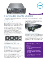
PowerEdge C5000
Brand: Dell Pages: 2

Accelar 8006
Brand: Nortel Pages: 4


