1
FRESH IN
TM
FIN-6MD
I
nstallatIon
I
nstructIons
Please take note that this manual uses the following symbols to emphasize particular information:
⚠
WARNING
Identifies an instruction which, if not followed, might cause serious personal
injuries including possibility of death.
CAUTION
Denotes an instruction which, if not followed, may severely damage the unit
and/or its components.
💡
Indicates a supplementary information that may relate to optional parts or
simply aim to facilitate a task.
⚠
WARNING
TO REDUCE THE RISK OF FIRE, ELECTRIC SHOCK, OR INJURY TO PERSON(S) OBSERVE THE
FOLLOWING:
1. Use this unit only in the manner intended by the manufacturer. If you have questions, contact the
manufacturer.
2. Before cleaning this unit, turn off the power to the AHU at service panel. (Powered by AHU)
3. This unit is not designed to provide combustion and/or dilution air for fuel-burning appliances.
4. Installation work must be done by qualified person(s) in accordance with all applicable codes and standards,
including fire-rated construction.
5. When cutting or drilling into a wall or ceiling, do not damage electrical wiring and other hidden utilities.
6. When cleaning or performing installation of this unit, it is recommended to wear safety glasses and gloves.
7. When applicable local regulation comprises more restrictive installation and/or certification requirements,
the aforementioned requirements prevail on those of this document and the installer agrees to conform to
these at his own expense.
8. The unit must be mounted at least 3.3 feet (1.0 meter) away from any accessible opening of the duct.
9. Must be powered using a Class 2 transformer rated 10VA or higher.
CAUTION
1. Please read specification label on product for further information and requirements.
2. Do not intake air into spaces within walls or ceiling or into attics, crawl spaces, or garage. Do not attempt
to recover the exhaust air from a dryer or a range hood.
3. Intended for residential installation only in accordance with the requirements of NFPA 90B.
4. When leaving the house for a long period of time (more than two weeks), a responsible person should
regularly check if the unit operates adequately.
5. At least once a year, the unit mechanical and electronic parts should be inspected by qualified service
personnel.
6. Since the electronic control system of the unit uses a microprocessor, it may not operate correctly because
of external noise or very short power failure. If this happens, turn power off at AHU service panel and wait
approximately 10 seconds. Then, restore the power to the unit.
7. Outdoor intake hood must be weather tight and comprise a bird screen.
8. Should you decide to dispose of this unit or of parts of it, do so in accordance with local laws and regulation.
⚠
RESIDENTIAL USE ONLY
⚠
For complete warranty statement, and to register your
product online, go to www.broan-nutone.com.
READ AND SAVE THESE
INSTRUCTIONS
1. PREPARATION
Before you start:
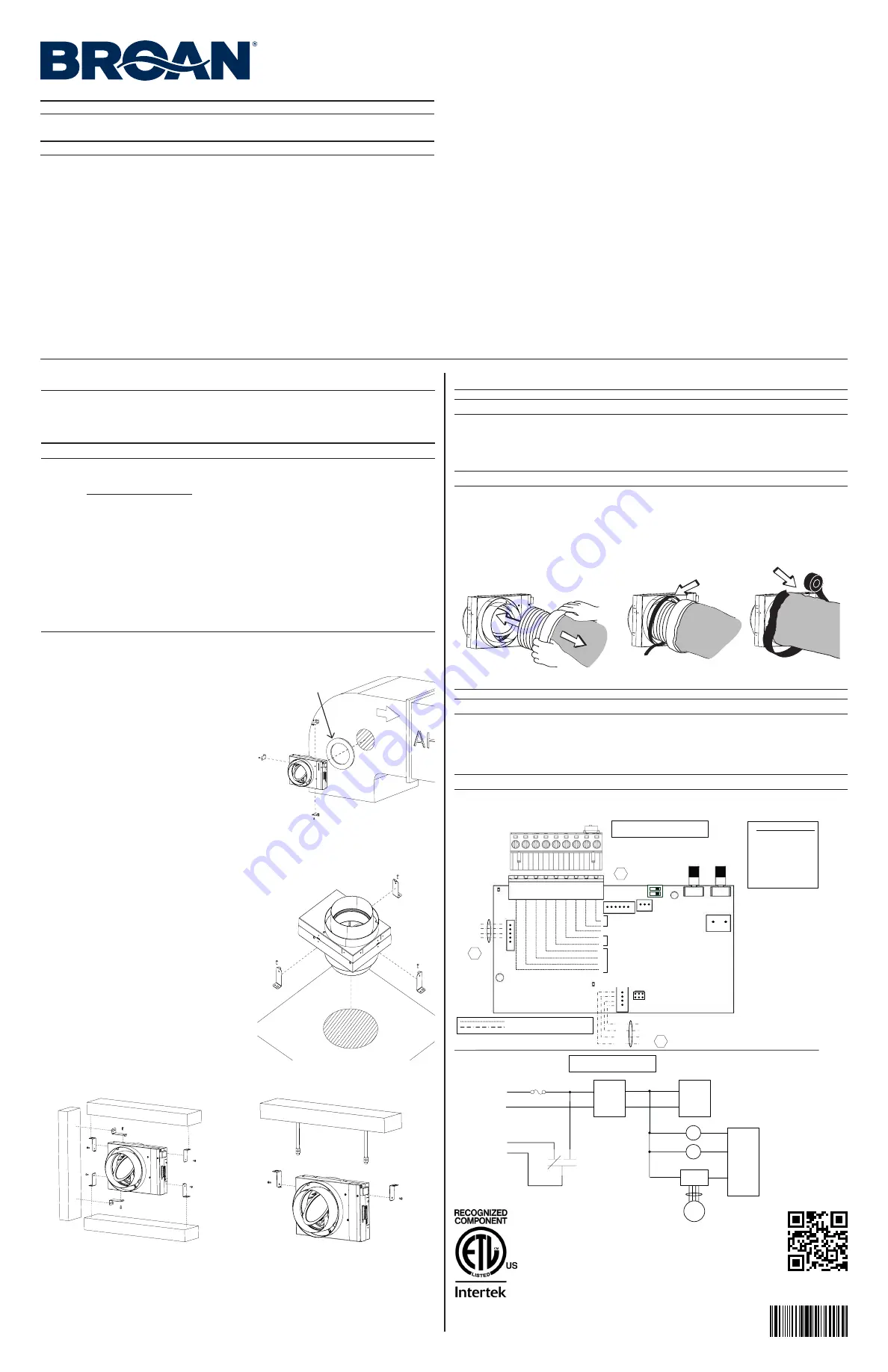
Choose the best location and installation type for the FIN-6MD according to the current system. Ducting
widely affects the performance of this type of device. Use the shortest, straightest duct run possible to
maximize the results.
CAUTION
Do not install in an area where the temperature may exceed 160°F.
The installer shall ensure that, if necessary, an in-line heater sized according to the required airflow and outside
design heating temperature from Manual J or ASHRAE table is installed to ensure that the air delivered to the
AHU is never below the minimum temperature allowed by the manufacturer. The in-line heater shall have an
integrated airflow sensor and an over temperature sensor to prevent heating in no-flow or low-flow conditions.
When deciding if a preheater is required and whether it should be installed BEFORE or AFTER the FIN-6MD,
consider the following:
• The FIN-6MD’s minimum operating temperature is -4°F.
• The temperature distributed to the AHU should never be below the temperature recommended by the
AHU manufacturer.
• The minimum distance between the preheater and the FIN-6MD is 12 inches.
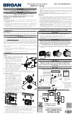
2. INSTALLATION
Always respect the orientation of the FIN-6MD and the direction of the airflow, as indicated on the
unit.
Direct-to-AHU is the fastest and easiest method:
1. Make a 6-inch diameter hole in the return duct of
your AHU.
2. Install the seal on the FIN-6MD port that will insert
the AHU ducting. Make sure that the direction of the
airflow indicated on the unit is respected.
3. Install the 3 installation brackets on the unit, as
illustrated.
4. Mark and drill holes for the brackets on the AHU
ducting and, using appropriate screws, secure the
FIN-6MD to the duct of the AHU, making sure it is
level horizontally.
💡
Use self-drilling screws (not included) to avoid
marking and drilling steps.
5. Follow steps in section 3 to connect the insulated
duct to the FIN-6MD.
6. Perform the electrical connection to the AHU following the wiring diagram in section 4.
Through a horizontal surface:
1. Make a hole in the surface that the duct will run
through. Size the hole so that the vapor barrier of the
insulated ducting is not damaged, and the insulation
not compressed.
2. Install the 3 installation brackets on the unit, as
illustrated.
3. Run a piece of insulated duct through the hole and
connect to the FIN-6MD following the steps in
section 3. Make sure the direction of the airflow as
indicated on the unit is respected.
4. Push the excess ducting on the other side of the
surface and, using appropriate screws, secure the
FIN-6MD to the surface.
5. Run the insulated duct to the AHU and connect to
the AHU ducting, making sure that the vapor barrier
sealing is leak-free.
6. Follow steps in section 3 to connect the second
insulated duct to the FIN-6MD.
7. Perform the connections to the AHU following the
wiring diagram in section 4.
Mounted under, above or beside a structure:
1. Install 2 installation brackets on the unit, as illustrated, according to the surface the unit will mount to.
2. Using appropriate screws, secure the FIN-6MD to the structure, making sure it is level horizontally. Make
sure the direction of the airflow as indicated on the unit is respected.
3. Follow steps in section 3 to connect both insulated ducts to the FIN-6MD.
4. Run the insulated duct to the AHU and connect to the AHU ducting, making sure that the vapor barrier
sealing is leak-free.
5. Perform the connections to the AHU following the wiring diagram in section 4.
UP
MOUNTED UNDER
MOUNTED ABOVE
MOUNTED BESIDE
SUSPENDED
LOGIC DIAGRAM
WIRING COLOR CODE
Reference : 1103507 rev. B
BLK
BLACK
BLU
BLUE
GRN GREEN
PNK
PINK
RED
RED
WHT WHITE
YEL
YELLOW
Low voltage factory wiring
Low voltage field wiring
1
J1
1
1
J7
J9
1
J5
1
LED1
(power)
LED2
(Status)
1
J4
1
9
M1
RED
BLU
YEL
PNK
Damper Motor
Harness
Y
W
Gf
G
R
C
Standby Switch
SO
SI
AHU Wiring
A1
ELECTRONIC
ASSEMBLY
Mode
Selection
CFM Ratio/
Damper
Selection
Power
Supply
(12V)
Low Voltage
(24VAC)
Class 2, 10 VA min.
K2
R
C
G
Gf
PTC
J4-7
J4-6
J4-4
J4-5
Power
Supply
(3.3V)
MCU
K1
K2
M1
Stepper
Driver
J5-1,2,3,4
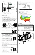
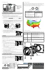
WIRING DIAGRAM
Not Used
J6
Humidity/
Temperature
Sensor
S1
GRN
RED
WHT
BLK
MCU
+24VAC Supply Class 2, 10VA min.
3. CONNECTING THE INSULATED DUCTS TO THE UNIT
CAUTION
Always use insulated ducting of a minimum R-4 insulation factor.
1. Slide the inner flexible duct over the port and secure it using a tie wrap.
2. Pull the insulation over the flexible duct and port without compressing it.
3. Use duct tape to seal the outer membrane of the insulated duct to the outer ring of the port.
⚠
WarnInG
Make sure the outdoor intake hood is at least 18 inches above the ground and 6 feet away
from any of the following: Dryer exhaust, high-efficiency furnace vent, central vacuum vent,
gas meter exhaust, gas barbecue-grill, any exhaust from a combustion source, garbage bin
and any other source of contamination.
💡
Make sure that the outdoor intake hood is easily accessible for annual maintenance. If located above the
first floor, place it close to a window or balcony to allow easy access.
4. WIRING DIAGRAM
⚠
WarnInG
Risk of electric shock. Electrical wiring must be done by qualified personnel in
accordance with all applicable codes and standards. Before connecting wires, switch off
the power to the AHU at service panel and lock service disconnecting means to prevent
power from being switched on accidentally.
CAUTION
Faulty connections can cause damage to the AHU, to the thermostat and/or to this unit.
Always double check connections before turning power back on.
Scan to view our
installation video.
5011110
CONFORM TO
UL STD. 1995
💡
The terminal block can
be removed for easier
connection.
💡
Use the included tie
wrap and the loop
above the terminal
block to secure the
wires and reduce
the risk of broken
connections.
Seal
AHU wiring next page
1103500B


