11
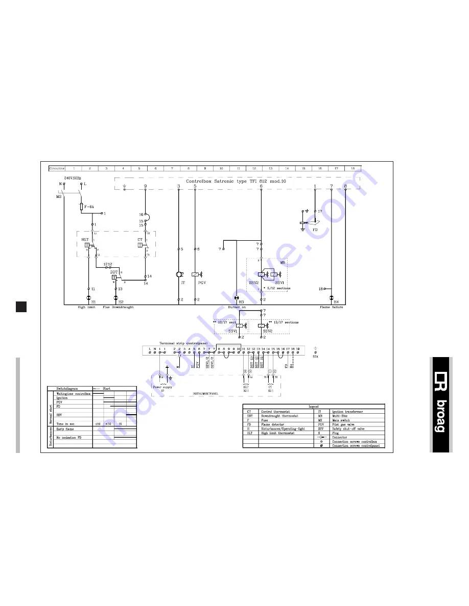
Fig. 10 Wiring diagram for the boiler with simple instrument panel
9.6 Wiring diagram boiler
9.6.1 Complete wiring diagram for On/Off boiler with
simple instrument panel
Страница 1: ...Atmospheric gas boiler 92 372 kW remeha Gas 3c Technical information ...
Страница 2: ...elines 8 7 1 General 8 7 2 Boiler assembly 8 7 3 Water connections 8 7 4 Pocket for instrument panel 8 7 5 Water pressure 8 8 Gas supply 9 8 1 General 9 8 2 Gas pressure 9 9 Electrical supply 9 9 1 General 9 9 2 Control panel 9 9 3 Electrical connections 9 9 4 Electrical data 9 9 5 Wiring diagram for the instrument panel 9 9 5 1 Simple instrument panel 9 9 5 2 Complete instrument panel On Off or H...
Страница 3: ...1 General Boiler block of cast iron sections are joined together with conical nipples Gas train and water connections can be fitted on either side of the boiler The gas train should as standard always be fitted on the same side as the instrumental panel thermostat pocket and the flow Instrument panel is fitted in the front casing Cleaning of the cast iron block from top of the boiler If you have a...
Страница 4: ...5 19 24 29 34 40 46 52 59 16 24 36 48 60 76 96 116 136 160 186 208 236 Water resistance 114 142 170 200 228 258 286 315 343 369 399 426 454 5 6 7 8 9 10 11 12 13 14 15 16 17 92 115 138 162 186 210 234 256 280 301 325 348 372 1015 1015 1040 1040 1040 1040 1065 1065 1065 1065 1090 1090 1090 675 775 875 975 1075 1175 1275 1375 1475 1575 1675 1775 1875 200 200 200 250 250 250 300 300 300 300 350 350 3...
Страница 5: ...DM2 Important The remeha Gas 3c is certified appliance and must not be modified or installed in any way contrary to these Installation and Servicing Instructions Manufacturers instructions must NOT be taken in any way as overriding statutory obligations 93 m3 h This minimum flow must be maintained for 5 minutes af ter the burner stops firing to avoid high temperature shut down due to residuel heat...
Страница 6: ...ler room back to back Fig 04 Installation 3 Number of sections 5 6 7 8 9 10 11 12 13 14 15 16 17 1015 675 200 1220 1015 775 200 1220 1040 875 200 1220 1040 975 250 1220 1040 1075 250 1220 1040 1175 250 1220 1065 1275 300 1320 1090 1875 350 1320 1090 1775 350 1320 1090 1675 350 1320 1065 1575 300 1320 1065 1475 300 1320 1065 1375 300 1320 Dimensions mm A B Ø D E ...
Страница 7: ...lugs The capillaries from the control panel should be fitted in the pocket of the boiler wich is fitted in the top front of the end section The instrument panel pocket and the flow should always be fitted at one side of the boiler either left or right and standard on the same side as the gas train Fig 05 Layout of the complete instrument panel B D E C A 1 3 5 4 2 6 8 7 9 11 10 The modules contain ...
Страница 8: ... pressure for the assembled boiler block is 6 bar Operating pressure between 0 8 bar and 6 bar 7 ASSEMBLY AND INSTALLATION GUIDELINES 6 3 Standard electronic gas train On Off or High Low 6 3 1 Schematic construction 6 3 2 Specification 1 Gas multibloc 5 12 sections 2 Safety shut off valves 13 17 sections 1 Gas governor 13 17 sections 1 Pilot gas valve 1 Pilot gas governor 1 Ignition transformer 5 ...
Страница 9: ... should be conform to the British Gas safety regulations 8 2 Gas pressure Maximum gas pressure at inlet 100 mbar Burner pressure full load 11 8 mbar 100 part load High Low version only 4 2 mbar 60 injector size 4 4 mm Ø Legend CT Control thermostat HLT High limit thermostat H LT High Low thermostat S Plug Connector 9 1 General The electrical installation must conform to the IEE regulations and als...
Страница 10: ...10 remeha Gas 3c 9 5 2 Complete instrument panel On Off or High Low Fig 09 Wiring diagram for the complete instrument panel Only High Low ...
Страница 11: ...11 Fig 10 Wiring diagram for the boiler with simple instrument panel 9 6 Wiring diagram boiler 9 6 1 Complete wiring diagram for On Off boiler with simple instrument panel ...
Страница 12: ...12 remeha Gas 3c 9 6 2 Complete wiring diagram for On Off boiler with complete instrument panel High Low thermostat will not be used Fig 11 Wiring diagram for the boiler with complete instrument panel ...
Страница 13: ...13 9 6 3 Complete wiring diagram for High Low boiler with simple instrument panel Fig 10 Wiring diagram for the boiler with simple instrument panel ...
Страница 14: ...14 remeha Gas 3c 9 6 4 Complete wiring diagram for High Low boiler with complete instrument panel Fig 11 Wiring diagram for the boiler with complete instrument panel ...
Страница 15: ...ler is on 9 Leave the boiler on for a couple of minutes to get rid of air in the gas pipe 10 Set the correct burner pressure 11 Check the thermostats for correct operation 12 Check the flame protection start the boiler with disconnected ionisation probe 10 3 Switching off the boiler 1 Switch off the electrical supply 2 Turn off the gas cock 10 COMMISSIONING 11 1 General It is essential for a good ...
Страница 16: ...chnical descriptions furnished by us remain our property and shall not be multiplied without our prior consent in writing ISO 9001 since 1988 Broag Ltd Head office Remeha house Molly Millars Lane Wokingham Berkshire RG41 2QP Tel 0118 9783434 Fax 0118 9786977 Branch office Unit 3 Kestrel Close Quarry Hill Ind Estate Ilkeston Derbyshire DE7 4RD Tel 0115 9440778 Fax 0115 9440588 ...