e-mail:
[email protected]
voice:
360.854.9559
fax:
866.783.1742
11
SS 2.1 MLR/BNC Installation and Operation Manual
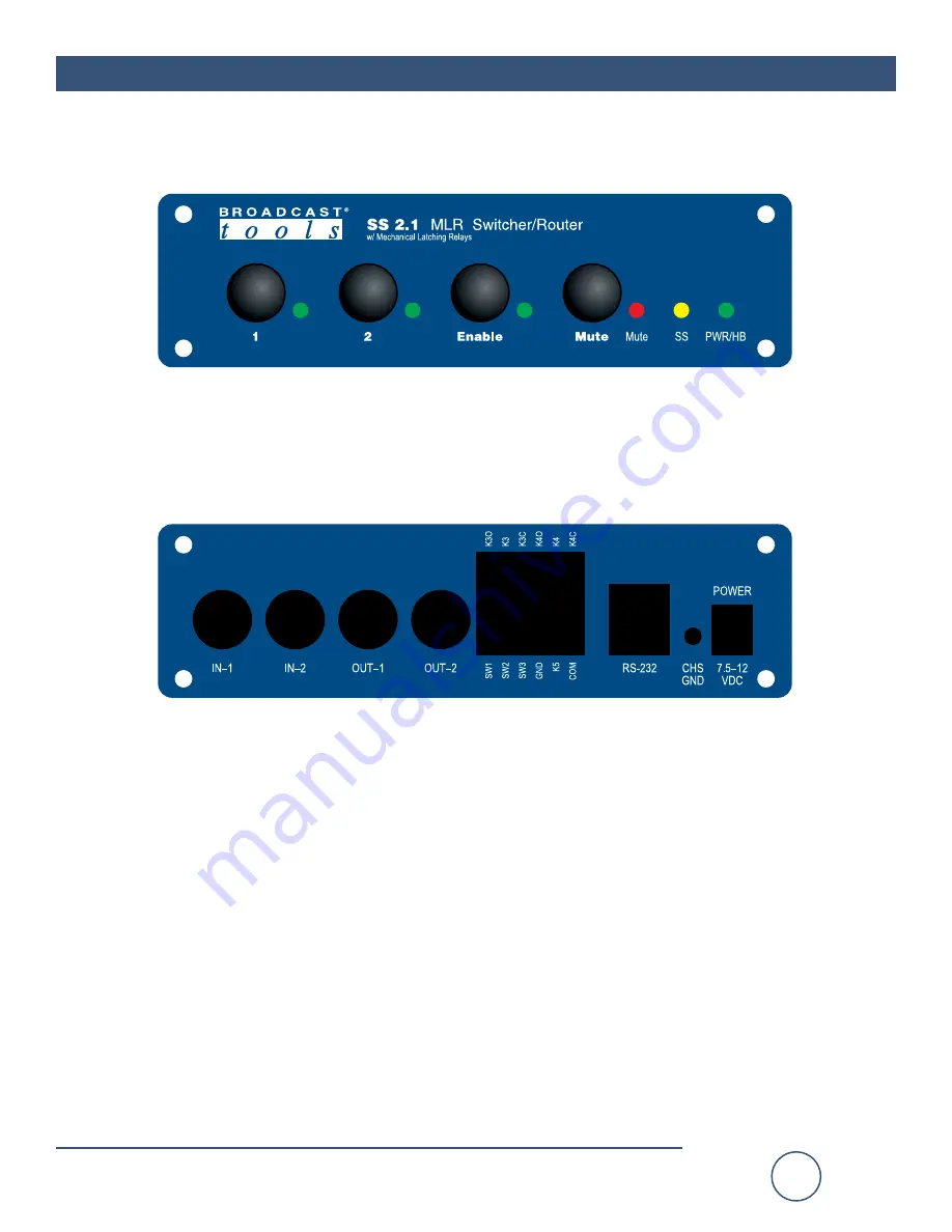
APPENDIX
FRONT PANEL
REAR PANEL
Страница 1: ...ols Inc All Sentinel labeled products are registered trademarks of Broadcast Tools Inc Copyright 1989 2012 by Broadcast Tools Inc All rights reserved No part of this document may be reproduced or distributed without permission Visit www broadcasttools com for important product update information Manual update 09 04 2012 If you need a firmware upgrade contact Broadcast Tools No part of this documen...
Страница 2: ...ower system 5 Installation Operation 5 Selection push buttons 5 Led indicators 5 Power 5 I O and Remote Control Connectors 6 Remote Control Wiring 6 Control 6 Relays 6 Configuration Jumpers 6 Configuration dip switch setup 7 Serial Operation 7 RS 232 Control 7 Serial commands 8 Menu Operation 8 Specifications 9 Warranty 10 Front and rear panel drawing Appendix Fractional schematic Appendix Configu...
Страница 3: ...e Broadcast Tools product Broadcast Tools Inc is unable to support NON Broadcast Tools software hard ware or NON Broadcast Tools computer hardware software problems If you experience these problems please research your hardware software instruction manuals or contact the manufacturers technical support department WHO TO CONTACT FOR HELP If you have any questions regarding your product or you need ...
Страница 4: ...te control via contact closures 5 volt TTL CMOS logic levels and or the multi drop RS 232 serial port TCP Telnet control monitoring with our option al ESS 1 RS 232 to Ethernet adapter Two SPDT relay outputs for remote channel status Audio signal switching via mechanical latching sealed relays utilizing 2 form C bifurcated crossbar silver alloy with gold overlay contacts BNC connectors are used for...
Страница 5: ... AUPS helps minimize the risk to the SS 2 1 MLR BNC and provides power during a power outage NOTE If power is lost the last selected channel is passed to the output Installation Operation Selection push buttons Each push button represents an input to be routed to the switcher s output along with the mute and enable push button Each push button has an associated LED indicator which will illuminate ...
Страница 6: ...emote Control The remote control connection to the switcher is via the bottom row of the connec tor TB4 Each channel may be selected by a momentary or sustained depending on the configuration contact to ground Each channel is pulled high 5 volts through a 22K resistor Relays SPDT relay contacts are available on the top row of the remote control connector TB4 K3 is associated with input channel one...
Страница 7: ...hannel 1 Pulse IN 2 to select channel 2 or pulse the M IN mute pin to turn off both channels Sustained operation mode Hold IN 2 low to select channel 2 Toggle operation mode Alternately pulse 1 IN to select between the two channels Note After changing any dipswitch please repower the unit Note Denotes factory setting SERIAL OPERATION RS 232 Control Connect one end of the modular cable to the RJ11 ...
Страница 8: ...ay unit ID in appropriate time slot U Enter menu mode Examples 02 This string would turn on channel 2 0M This string would MUTE the switcher s output 0U Accesses the menu NOTE The menu times out after 60 seconds of keyboard inactivity Menu Operation Broadcast Tools SS 2 1MLR BNC v1 9b Setup Menu S Turn ON audio input M Turn OFF audio V Save Audio State for Power Up C Show Configuration and Status ...
Страница 9: ...mpatible with 5 volts CMOS TTL logic open collector or contact closures to ground Serial Multi drop RS 232 2400 9600 19200 38400 8 N 1 Status Front Panel LED Indicators Remote Two SPDT relays 1 amp 30 vdc Refer to the fractional schematic and or text on the rear panel for con nection details Interfacing I O BNC Remote control Rear panel pluggable screw terminals Mating connectors supplied RS 232 R...
Страница 10: ... NO OTHER WARRANTIES OR REMEDIES TO THE MAXIMUM EXTENT PERMITTED BYAPPLICABLE LAW BROADCAST TOOLSAND ITS SUPPLIERS DISCLAIMALL OTHER WARRANTIES EITHER EXPRESS OR IMPLIED INCLUDING BUT NOT LIMITED TO IMPLIED WARRANTIES OF MERCHANTABIL ITY OR FITNESS FOR A PARTICULAR PURPOSE AND THE FOREGOING ALTERNATIVE REMEDIES SHALL BE EXCLUSIVE OF ALL OTHER REMEDIES THIS LIMITED WARRANTY GIVES YOU SPECIFIC LEGAL...
Страница 11: ...e mail support broadcasttools com voice 360 854 9559 fax 866 783 1742 11 SS 2 1 MLR BNC Installation and Operation Manual APPENDIX FRONT PANEL REAR PANEL ...
Страница 12: ...e mail support broadcasttools com voice 360 854 9559 fax 866 783 1742 SS 2 1 MLR BNC Installation and Operation Manual 12 APPENDIX ...
Страница 13: ...e mail support broadcasttools com voice 360 854 9559 fax 866 783 1742 SS 2 1 MLR BNC Installation and Operation Manual 13 APPENDIX ...
Страница 14: ...e mail support broadcasttools com voice 360 854 9559 fax 866 783 1742 SS 2 1 MLR BNC Installation and Operation Manual 14 APPENDIX ...