2.
INSTALLATION
Installing the CCU. Do not connect the mains supply to the CCU until all wiring
&
cabling is completed. First remove the cover by prising out the central BT logo button using a
Screwdriver Instrument No.
1,
loosen the cover fixing screw and lift the cover clear,
(see
fig.
1).
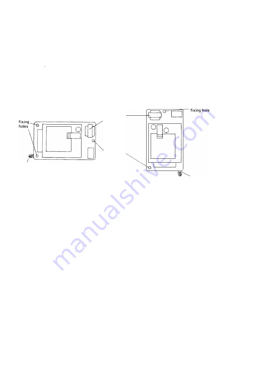
The CCU should be screwed to a suitable wall surface using the three fixing holes in
the base. To avoid overheating make certain that the mains transformer is at the top.
Fig 3
shows
the two permitted methods of mounting the CCU.
OOO
DOD
ODD
0 0
DOD
DODOO
mains
transformer
fixing hole
D
D
D D
c:::::J
D D
ODD
D D
ODD
ODD
cable entry
0
(a) horizontal mounting
F/G.3
(b) vertical mounting
cable entry
PERMITTED MOUNTING OF CCU
After fixing the CCU and before cabling the system, remove the cover from the mains cable
terminal blocks
(see
fig
2)
and check that the cable is correctly terminated with the
green yellow conductor to Earth ( E) term in al
Wiring
the brown conductor to
Live ( L) terminal
the blue conductor to
240V
terminal
After checking the terminations of the mains cable replace the terminal block cover.
All cables enter the CCU via slots in the lower edge (when mounted vertically) of the
back plate and are fed through guides on the right hand side of the unit. The cables terminate
under screw terminals on the appropriate terminal block
(see
fig.
2)
which are a push fit on
pins on the printed circuit boards.
Extensions are wired as ordinary two wire telephones with the cables connected to
terminals A and B of the terminal block. At the extension, cables may be either connected to
"Phonesocket" master line jacks or to block terminals if required. An extension may be
provided with two high impedance telephones connected as a Phonesocket installation, using
a secondary line jack for the additional telephone.
3.


