6
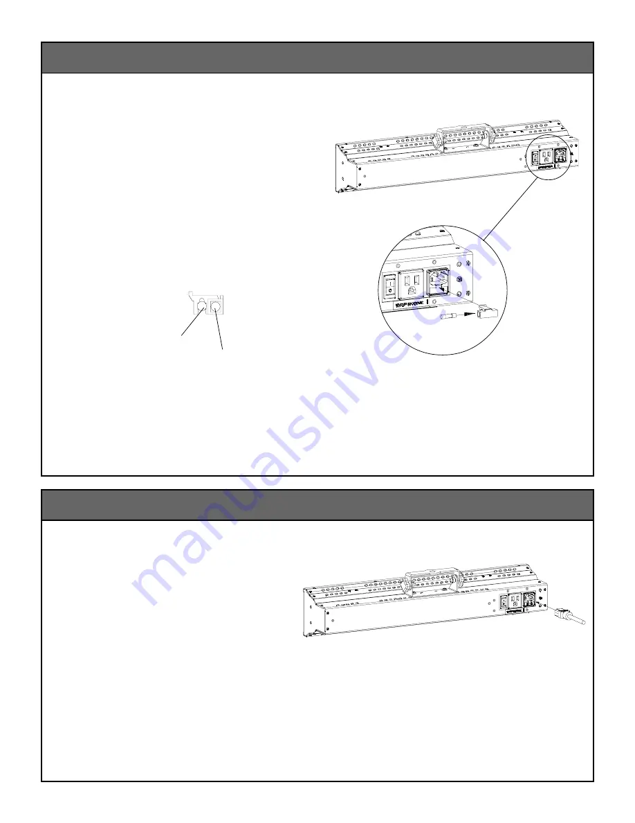
1. The IEC320 connector mates with the
power inlet module (Fig. 13).
Note: The ON/OFF switch should always
be in “OFF” position when installing
or removing the power cord.
Installing Power Cord
Replacing Fuse
1. Pull fuse holder out of power inlet
module.
2. Remove fuse holder and check for wear (Fig. 11).
If fuse is blown, replace with a new fuse or the
on-board spare (Fig. 12).
3. Return fuse holder to a closed position.
Figure 13
Note: Replace fuse only with 5-amp, time-delay,
250-volt, 5 x 20-mm fuses.
Figure 11
On-board Spare
Active Fuse
Figure 12
Содержание 1.1N
Страница 9: ...9 Wiring Diagram NonDim...
Страница 11: ...11 Notes...


