background image

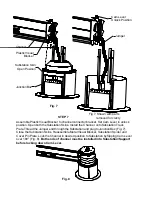
Fig. 7

Fig 7. Shown with parts
          removed for clarity

Channel

Cam Lever
Unlock Position

Jumper

Substation Skin

Open Position

Junction Box

STEP 7

Assemble Plastic Visual Blocker to channel connector bracket. Set Cam Lever in unlock
position. Open both the Substation Skins. Install  the Channel  onto Substation Track
Plate.Thread the Jumper end through the Substation and plug to Junction Box (Fig. 7).
Close the Substation Skins. Reassemble Metal Visual Blocker, Substation Spider and
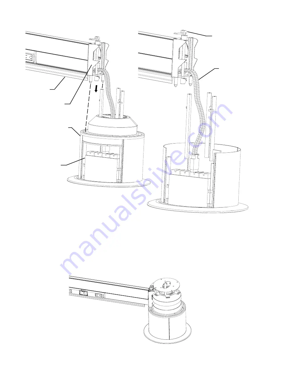
Cover Pin Plate. Lock the Channel in desired position to Substation by flipping Cam Lever
over 180° (Fig. 8). Both ends of channel must be installed into Substation/Support
before locking down Cam Lever.

Fig. 8

Plastic Visual

Blocker

Содержание M-SUB

Страница 1: ...SUBSTATION AND CHANNEL MODEL Assembly Instructions TOOLS REQUIRED 1 2 WRENCH PHILIPS SCREWDRIVER 3 8 WRENCH ELECTRIC HAND DRILL LIQUID WORKSPACE M SUB...

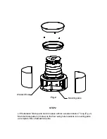
Страница 2: ...kirt Remove Substation Top Cover by pulling it up Disassemble Substation Track Plate and Substation Skins by removing three Substation Track Plate screws Fig 1 Save hardware for reassembly Substation...

Страница 3: ...bstation Skirt up and hold it in place with two wooden blocks 7 long Fig 2 Mark bolt hole pattern 3 holes on the floor using hole locations in mounting plate as template Move Substation aside Wooden B...

Страница 4: ...2 concrete expansion anchor Drill holes and complete installation using hardware manufacturer s recommended proce dure b For wood floor Drill appropriate holes depending on type of wood for 1 4 x 2 la...

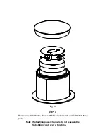
Страница 5: ...STEP 4 Remove wooden blocks Reassemble Substation skins and Substation track plate Fig 4 Note If attaching power channels do not reassemble Substation Top Cover at this time...

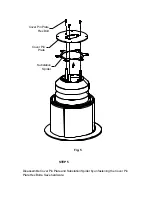
Страница 6: ...Cover Pin Plate Cover Pin Plate Hex Bolt Substation Spider STEP 5 Disassemble Cover Pin Plate and Substation Spider by unfastening the Cover Pin Plate Hex Bolts Save hardware Fig 5...

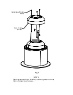
Страница 7: ...Metal Visual Blocker Metal Visual Blocker Screw STEP 6 Disassemble Metal Visual Blocker by unfastening the three Visual Blocker Screws Save hardware Fig 6...

Страница 8: ...Substation Skins Install the Channel onto Substation Track Plate Thread the Jumper end through the Substation and plug to Junction Box Fig 7 Close the Substation Skins Reassemble Metal Visual Blocker...

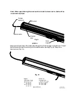
Страница 9: ...opening Fig 9 Snap close Channel door Fig 10 Fig 10 Part 031 6464 Rev 07 15 03 IM Bretford Bretford Ltd 11000 Seymour Avenue Technology House Franklin Park IL 60131 7 Lake End Court Taplow TEL 847 67...

Отзывы: