background image

INSTALLATION

6

3

INSTALLATION

3.1

Unpacking and Inspection

Follow the unpacking instructions on the packaging.
Check  that  your  delivery  is  correct  and  does  not  have
transport  damage.  Report  any  damage  immediately  to
your Bredel representative.
This  chapter  will  treat  the  installation  of  the  bare  shaft
set.  Refer  to  the  manual  of  the  pumphead  for
installation  and  setup  of  the  complete  pump  and  the
pipework.

3.2

Installation 

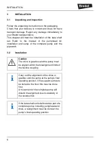
Caution

The drive or gearbox and the pump must 
be aligned within the misalignment limits of 
the flexible coupling.


Carry out the alignment of the drive or 
gearbox and the pump at the pump’s final 
operating position. If the support set has to 
be bolted to the floor this must be done 
first.
A movement of the complete pump will 
disturb the alignment due to elasticity of 
the construction.

If the bare shaft set is delivered as part of a 
complete pump, including pumphead and 
drive, a realignment must be done at the 
pump’s final operating position.

Содержание BREDEL PUMP Series

Страница 1: ...Copyright 2016 Watson Marlow Fluid Technology Group 28 1003210 BREDEL PUMP SERIES Additional information on Bredel 40 pump with bare shaft configuration...

Страница 2: ...Additional Information on Bredel 40 pump with bare shaft configuration Original Instructions...

Страница 3: ...s to all damage inclusive of without limitation compensating direct indirect or consequential damage loss of data income or profit loss or damage to possessions and claims of third parties Watson Marl...

Страница 4: ...the pumphead 7 3 2 2 Mounting and aligning the Drive 10 4 MAINTENANCE 4 1 Cleaning 13 4 2 Demounting the pumphead 13 4 3 Demounting the drive 14 4 4 Demounting the bare shaft hub 15 4 5 Disassembling...

Страница 5: ...of components such as pumps motors and inverters is normally not included in this manual However if additional documentation is supplied you must follow the instructions in this additional documentat...

Страница 6: ...drive Every other use is not in conformance with the intended use Refer to the manual of the pumphead for more information on safety and the intended use of the complete pump ENVIRONMENT Always obser...

Страница 7: ...or warranty conditions These conditions are applicable to the bare shaft set as well Damaged parts of the bare shaft set that are returned to the manufacturer must be accompanied by a fully filled in...

Страница 8: ...d The support set consists of two frame halves an adjustable drive support plate and a coupling guard The bare shaft kit consists of a shaft a hub a bearing and a seal No fasteners are provided for mo...

Страница 9: ...e pump and the pipework 3 2 Installation Caution The drive or gearbox and the pump must be aligned within the misalignment limits of the flexible coupling Carry out the alignment of the drive or gearb...

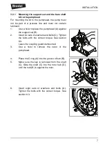
Страница 10: ...ert six sets of washers and bolts C Tighten the bolts with the correct torque See section 6 3 Leave the coupling guard demounted 3 Use a hoist to remove the cover of the pumphead 4 Place the O ring A...

Страница 11: ...ount of grease on the seal D 10 Make sure that the hub C contains the seal the bearing and the outer retaining ring Slide the hub C over the shaft B until it is against the hub A 11 Insert eight sets...

Страница 12: ...F on the threaded rod E Turn the nut F to drive the coupling half C onto the shaft 15 Fasten the setscrew B in the coupling half C 16 At the front of the pumphead check if the shaft in still correctly...

Страница 13: ...height loosen the 12 sets of fasteners A Move plate B up or down to the correct position and slightly tighten the fasteners A Check the height and repeat this step if necessary If the height is corre...

Страница 14: ...e sure that the coupling halves A and the spider mesh correctly 7 Use two alignment jigs D to check the alignment of the coupling halves in the vertical plane Looking from aside both coupling halves C...

Страница 15: ...support set using a punch and a hammer or a felt tip pen 12 Remove the alignment jigs and use a hoist to remove the drive 13 Drill holes with the correct diameter in the horizontal plate B at the mark...

Страница 16: ...the manual of the pump 2 Loosen the fasteners A of the coupling guard and remove the coupling guard B Warning When cleaning the pump do not use a high pressure spraying pistol This might damage the se...

Страница 17: ...nting the drive 1 Isolate the drive from the electrical supply 2 Loosen the fasteners A of the coupling guard and remove the coupling guard B Remove the fasteners C from the gearbox feet B A A To demo...

Страница 18: ...y away from the support set to separate the coupling halves A and B 4 4 Demounting the bare shaft hub 1 Loosen screw B and remove the coupling half A 2 Remove key B from the shaft end 3 Remove the eig...

Страница 19: ...bolts B until they touch the face of the pumphead to which the hub is mounted 6 Gently turn the bolts A alternately half a turn clockwise to press the hub from the pumphead 7 Once the bearing has bee...

Страница 20: ...the seal B from the hub A 4 6 Assembling the bare shaft hub Check the bearing and the seal before reuse If necessary use a new bearing and a new seal 1 Place the hub A on a flat surface with the beari...

Страница 21: ...o hub A until it rests on the collar Keep the closed side of the seal upward Apply an excessive amount of grease on the lip seal 3 Use a suitable tool to press bearing B into hub A until it rests on t...

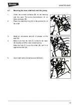
Страница 22: ...oil on these surfaces B 2 Place the retaining ring C in the groove A of the shaft 3 Apply an excessive amount of grease on the seal D 4 Make sure that the hub C contains the seal the bearing and the...

Страница 23: ...crew a threaded rod E into the shaft end Place the coupling half C on the shaft end Install a disc D and nut F on the threaded rod E Turn the nut F to drive the coupling half B onto the shaft 9 Fasten...

Страница 24: ...ng from above both coupling halves C must touch the edge of both jigs If necessary move the drive E over the plate B to accomplish this Axial radial and angular displacement of the coupling halves mus...

Страница 25: ...gnment jigs D to check the alignment of the coupling halves C in the horizontal and vertical plane Looking from above and from the side both coupling halves C must touch the edge of both jigs If neces...

Страница 26: ...ct torque See section 6 3 7 Place the coupling guard B Tighten the fasteners A with the correct torque See section 6 3 8 Connect the suction and discharge lines and open any shut off valves in these l...

Страница 27: ...tolerances as given in section 6 4 Poor misalignment will shorten the lifetime of the bearing in the bare shaft kit the bearing s in the gearbox and the spider in the flexible coupling Follow the che...

Страница 28: ...he pumphead Damaged bare shaft kit bearing Check the alignment See above Check the bearing and the seal and replace if necessary See chapter 4 Rattling or squeaking noise near the gearbox Damaged gear...

Страница 29: ...Support set Pos Qty Description Size Material 1 1 Pump support steel 2 1 Gearbox support steel 3 1 Coupling guard steel 4 4 Pin ISO 8750 8 x 24 steel 5 12 Thick flat washer M8 steel 6 12 Bolt M8 x 35...

Страница 30: ...al 1 1 Hub steel 2 1 Joint shaft steel 3 1 Bearing 6208 2RS1 steel 4 1 Radial shaft seal CR 40 x 60 x 10 HMS5 RG NBR 5 1 Retaining Ring DIN 472 80 x 2 5 Steel 6 1 Retaining Ring DIN 471 AV40 Steel 7 1...

Страница 31: ...or steel fasteners with metric thread 6 4 Coupling These are specifications of the flexible couplings which are delivered as part of a complete pump based on the bare shaft solution Bare Shaft Set Wei...

Страница 32: ...SPECIFICATIONS 29 Coupling size L mm E mm s mm Maximum displace ments Rated torque Nm Ka mm Kr mm Kw degrees 48 140 28 3 5 1 0 2 1 0 36 1 1 310...

Страница 33: ...30...

Страница 34: ...31...

Страница 35: ...tside of the packaging containing the item s The sender of the item s is responsible for cleaning and decontaminating of the item s before returning them in such way that it is safe for the receiver t...

Страница 36: ...33...
Страница 37: ...03210 TS16 027 Watson Marlow Bredel B V P O Box 47 NL 7490 AA Delden The Netherlands Telephone 31 0 74 3770000 Fax 31 0 74 3761175 E mail Bredel wmftg com Internet www wmftg com 2017 Watson Marlow Bre...

Страница 38: ...the right to alter speci cations without prior notice All mentioned values in this document are values under controlled circumstances at our test bed Actual ow rates achieved may vary because of chang...

Отзывы: