background image

MAINTENANCE

34

8

MAINTENANCE

8.1

General

Only use original Bredel parts when maintaining the
hose pump. Bredel cannot guarantee correct operation
and any consequential damage that occurs from the
use of non-original Bredel components. Also refer to
chapters 

2

 and 

3

.

Check that your delivery of original parts is correct and
check it for any transport damage. If parts are
damaged, consult your Bredel representative.

8.2

Maintenance and periodic inspections

The following diagram shows the maintenance and
periodic inspection that need to be carried out on the
hose pump to guarantee optimal safety, operation and
life of the pump.

WARNING

Disconnect and lock the power supply to 
the pump drive before any work is carried 
out.
In case the motor is fitted with a frequency 
controller and has a single-phase power 
supply, wait two minutes to make sure that 
the capacitors have discharged.

WARNING

Do not remove the pump cover if the power 
cable is connected to the motor. Do not 
connect the power cable to the motor if the 
pump cover is removed.

Before installation, always check the condi-
tion of the supplied parts. Do not install 
damaged parts. In case of doubt, contact 
your Bredel representative.

Содержание APEX28

Страница 1: ...ione del manuale nella propria lingua utilizzare il disco o acquisire il codice QR Chcete li z skat p eklad p ru ky ve va em jazyce pou ijte disk nebo naskenujte QR k d Ha a k zik nyvet saj t nyelv n...

Страница 2: ...and then the required language 3 Open or save the user manual The PDF reader program shows the selected user manual How to use the QR code 1 Scan the QR code with your smartphone or tablet The app fo...

Страница 3: ...3 Hose pump series APEX28 and APEX35 Installation Operation and Maintenance Manual Environmental Management ISO 14001 Quality Management ISO 9001...

Страница 4: ...s to all damage inclusive of without limitation compensating direct indirect or consequential damage loss of data income or profit loss or damage to possessions and claims of third parties Watson Marl...

Страница 5: ...DESCRIPTION 4 1 Identification of the product 14 4 1 1 Identification of the product 14 4 1 2 Identification of the pump 14 4 1 3 Identification of the gearbox 14 4 1 4 Identification of the electric...

Страница 6: ...ure 31 7 6 Fluid leakage 33 8 MAINTENANCE 8 1 General 34 8 2 Maintenance and periodic inspections 34 8 3 Cleaning the pump hose 36 8 4 Changing lubricant 36 8 5 Replacing the pump hose 37 8 5 1 Removi...

Страница 7: ...5 Weights 61 11 1 6 Torque figures 62 11 2 Lubricant table gearbox 63 11 3 Gearbox 64 11 4 Electric motor 64 11 5 Variable Frequency Drive VFD optional 64 11 6 Parts list 65 11 6 1 Ordering parts 65 1...

Страница 8: ...al are a translation of the original instructions 1 3 Other supplied documentation Documentation of components such as the gearbox the motor and the frequency controller is not included in this manual...

Страница 9: ...tor Refer to 4 1 1 1 5 Environment and disposal of waste Inquire within your local government about the possibilities for reuse or environment friendly processing of packaging materials contaminated l...

Страница 10: ...cations of the manufacturer inclusive of his indications in the sales brochure In case of doubt it is the use which appears to be its intended use judging from the construction execution and function...

Страница 11: ...accept any responsibility for damage or harm caused by not observing the safety regulations and instructions in this manual and other supplied documentation or by negligence during installation use ma...

Страница 12: ...rsons in training may use the hose pump only under the supervision and responsibility of trained and qualified users 2 6 Regulations and instructions Everyone who works with the hose pump must be awar...

Страница 13: ...n and signed safety form as present in the back of this manual The safety form must be applied to the outside of the shipping carton Parts which have been contaminated or which have been corroded by c...

Страница 14: ...ncy controller option 4 1 2 Identification of the pump The identification plate on the pumphead contains the following data A Pump type and rotor type low or medium pressure B Serial number 4 1 3 Iden...

Страница 15: ...the VFD Remove the cover by loosening the two screws The identification sticker contains the following data A Article number B Serial number 4 1 6 Identification of the pump hose The identification st...

Страница 16: ...DESCRIPTION 16 4 2 Construction of the pump A Cover B Rotor C Pump hose D Pump housing E Supports F Gearbox G Electric motor H Frequency controller A D C E G E F H B...

Страница 17: ...e As soon as the shoe has passed the hose recovers to its original shape due to the mechanical properties of the material and fluid is drawn into the hose In phase 2 fluid is drawn through the hose by...

Страница 18: ...redel pump hoses have been carefully machined to achieve minimum tolerances in wall thickness It is very important to guarantee the correct compression of the pump hose because When the compression is...

Страница 19: ...essure If you want to change the application of your hose pump contact your Bredel representative 4 4 3 Lubrication and cooling The pumphead is filled with Bredel Genuine Hose Lubricant This lubricant...

Страница 20: ...tandard electric motor is a completely enclosed three phase asynchronous motor The motor connection must meet the local applicable regulations Refer to the documentation supplied with the electric mot...

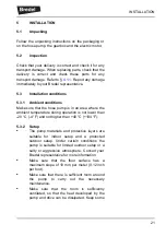
Страница 21: ...an area where the ambient temperature during operation is not lower than 20 C 4 F and not higher than 40 C 104 F 5 3 2 Setup The pump materials and protective layers are suitable for indoor setup and...

Страница 22: ...suction lines as short and direct as possible It is recommended to use a minimum of three quarters 3 4 of the hose length as flexible hose in the suction or discharge line This avoids the need to remo...

Страница 23: ...ly 5 3 5 Frequency controller If the hose pump is fitted with a frequency controller consider the following points Take precautions so the motor does not restart automatically after an unscheduled sto...

Страница 24: ...r lifting and moving the hose pump The complete hose pump i e pumphead gearbox and electric motor must be lifted using the lifting eyes and suitably rated straps or slings A For the weights refer to 1...

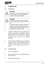
Страница 25: ...ill with Bredel Genuine Hose Lubricant via the breather plug Also refer to 8 4 6 2 Commissioning 1 Connect the pipework 2 Make sure that there are no obstructions such as closed valves 3 Switch on the...

Страница 26: ...from your specification follow the instructions in chapter 10 or consult your Bredel representative 6 If a frequency controller is present check the capacity range In case of any deviations consult th...

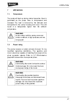
Страница 27: ...operating condition s The gearbox and motor should be capable of handling that power at the given revolution speeds Refer to 7 3Performance graphs28 to determine the required power WARNING Avoid conta...

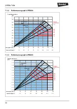
Страница 28: ...psi lines describes the allowed performance area The required duty points have to fall within this area In the direction of higher speeds and powers pump operation is limited by the heat generated th...

Страница 29: ...mp speed A 2 Meet the line of the required discharge pressure B 3 Read the required motor power C To determine maximum allowed pump speed 1 Start at the product temperature D 2 Meet the line of the re...

Страница 30: ...1 00 1 25 1 50 1 75 2 00 2 25 2 50 2 75 Required motor power HP Product temperature F 104 122 140 158 176 Con nuous Duty Intermi ent Duty Intermi ent Duty Con nuous Duty 0 20 40 60 80 100 120 140 Pump...

Страница 31: ...it is advisable to minimise dry running periods 7 5 Hose failure Cause of a hose failure The hose in a peristaltic pump has to withstand many load cycles of considerable magnitude The repetitive stre...

Страница 32: ...ct outside the pump Reversed flow protection is advised This is not part of the scope of delivery A high level float switch can be applied to detect fluid escaping through the breather Refer to 8 7 1...

Страница 33: ...ose failure and regular replacement of the lubricant is strongly advised The pumphead and gearbox are directly coupled to each other A special feature is included in the pumphead to allow early detect...

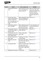
Страница 34: ...nance and periodic inspection that need to be carried out on the hose pump to guarantee optimal safety operation and life of the pump WARNING Disconnect and lock the power supply to the pump drive bef...

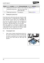
Страница 35: ...ore starting the pump and at scheduled inter vals during operation In case of leakage con sult your Bredel repre sentative 4 Checking the pump for deviating temperature or strange noises At scheduled...

Страница 36: ...the pump hose immediately once the pump is stopped to avoid sedimentation and or hardening of the product within the hose that can cause damage upon restart 8 4 Changing lubricant 1 Place a tray A und...

Страница 37: ...hose 8 5 1 Removing the pump hose 1 Isolate the pump from the electrical supply 2 Close any shut off valves in the suction and discharge line to minimise product loss 3 Place a tray A under the drain...

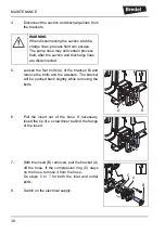
Страница 38: ...nsert the tip of a screwdriver behind the flange of the insert 7 With the insert B removed pull the bracket A off the hose If the compression ring C stays on the hose remove it from the hose Do steps...

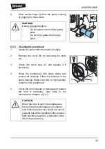
Страница 39: ...pump housing Make sure that no rinsing water remains in the pumphead 5 Check the rotor for wear or damage and replace the rotor if necessary Also refer to the maintenance diagram in 8 2 A WARNING Duri...

Страница 40: ...at the rotor pulls the hose into the pump housing Stop the motor when the hose sticks out equally from both sides of the pump housing 4 Check that the rubber compression rings A are not deformed or da...

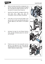
Страница 41: ...n ring is not already compressed 8 If the hose is not yet at its end position then turn the rotor in such a way that the hose A is pressed against its end position in the bracket B 9 Lubricate the ins...

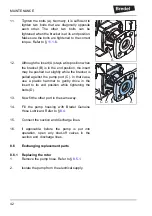
Страница 42: ...htly while the bracket is pulled against the pump port C In that case use a plastic hammer to gently drive in the insert to its end position while tightening the bolts D 13 Now fit the other port in t...

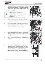
Страница 43: ...pump shaft C 6 Check the outside of the dynamic seal A for deformation or damage as far as possible The dynamic seal is partly covered by the pump shaft Replace the dynamic seal if necessary Refer to...

Страница 44: ...l supply to the pump 10 Fit the new pump hose Refer to 8 5 3 8 6 2 Replacing the bearing seal ring shaft and coupling bush 1 Remove the hose the cover and the rotor Refer to 8 6 1 steps 1 to 5 2 Remov...

Страница 45: ...he pump shaft if necessary 7 At the back of the pump housing drive out the dynamic seal A via the paths of the leakage zone B Use a driver and a plastic hammer 8 If it is not necessary to replace the...

Страница 46: ...l the circlip A in the groove of the pump housing B 13 Slightly grease the sealing lip of the new dynamic seal A Do not grease the outside surface of the dynamic seal Fit the dynamic seal from the fro...

Страница 47: ...inner circlip C at the front end and an outer circlip A at the back end 18 If necessary slightly grease the output shaft of the gearbox and position the new coupling bush on it Use a plastic hammer to...

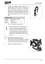
Страница 48: ...ers and bolts A and tighten the bolts to the correct torque Refer to 11 1 6 21 Install the rotor the cover and the hose Refer to 8 6 1 steps 6 to 10 8 7 Fitting options 8 7 1 Fitting a high level floa...

Страница 49: ...lution counter 1 Jog the rotor until the pressing shoe is clearly visible through the inspection window Now the pressing shoe faces the position of the sensor 2 Remove the lubricant Refer to 8 4 NC Sp...

Страница 50: ...ling ring A on the new sensor C 6 Install the sensor C in the pump housing 7 Turn the sensor so that the distance between the sensor and the rotor X is between 0 75 mm 0 03 in and 1 25 mm 0 05 in Tigh...

Страница 51: ...the correct order diagonally opposite each other Refer to 11 1 6 10 Refill the pump housing with lubricant Refer to 8 4 11 Connect the sensor electrically via the 2 meter 7 feet long PVC cable 3 x 0 3...

Страница 52: ...of untreated parts For this purpose use the correct protection or packaging After a long period of standstill or storage the static load on the pump hose may have caused permanent deformation which wi...

Страница 53: ...phase power supply wait two minutes to make sure that the capacitors have discharged Problem Possible cause Correction Failure to operate No voltage Check if the power supply switch is on Check if th...

Страница 54: ...re too high Consult your Bredel repre sentative about the maxi mum temperature range of the fluid Internal friction on the hose caused by blocked or poor suction characteristics Check pipework valves...

Страница 55: ...relation to the vis cosity of the product to be pumped and the inlet pres sure The suction line can be too long or too narrow or a combination of these fac tors Consult your Bredel repre sentative fo...

Страница 56: ...he pressure relief valve functions prop erly if present in the dis charge line High product temperature Consult your Bredel repre sentative for correct hose selection High pulsations Restructure the d...

Страница 57: ...ockages and replace if necessary Bolts of bracket loose Tighten to the specified torque settings Refer to 11 1 6 Leakage from the rear of the pump housing Buffer zone Damaged seal ring Replace seal ri...

Страница 58: ...ll to cool down for at least one hour after three hours of operation m3 h 3 4 6 2 US gpm 15 2 27 3 Capacity per revolution l rev 0 36 0 74 US gal rev 0 095 0 195 Max permissible working pressure with...

Страница 59: ...dow PMMA 4 Pump rotor Aluminium 5 Pump supports Galvanised steel AISI 316 optional 6 Brackets Cast iron 7 Fasteners Galvanised steel AISI 316 optional 8 Dynamic seal behind the rotor NBR 9 Cover seal...

Страница 60: ...h this lubricant must be checked if applied Refer to the chemical compatibility chart at www wmftg com chemical or contact your Bredel representative for guidance Unit APEX28 APEX35 Lubricant Bredel G...

Страница 61: ...kg 51 75 lbs 112 165 Pump supports total weight for 2 supports kg 4 5 5 5 lbs 9 9 12 1 Rotor kg 3 8 5 8 lbs 8 4 12 8 Hose kg 1 9 2 6 lbs 4 2 5 7 Pump cover complete kg 3 5 4 2 lbs 7 7 9 3 Shaft and c...

Страница 62: ...s Description Unit Torque Nm APEX28 APEX35 1 Cover Nm 20 35 lbf in 180 310 2 Bracket Nm 25 50 lbf in 220 440 3 Supports Nm 25 50 lbf in 220 440 4 Gearbox Nm 25 50 lbf in 220 440 5 Inspection window Nm...

Страница 63: ...axial gearboxes For a complete overview of the recommended lubricants contact your Bredel representative Oil type Mineral oil Synthetic oil Change oil every 5000 hours 20 000 hours Ambient temperatur...

Страница 64: ...o or three Mounting position IM 3001 IM B5 flanged gearbox with keyed shaft in horizontal position Motor adapter Integrated Optional motor adapter Adapter in conformance with IEC B5 or NEMA C In case...

Страница 65: ...mp size APEX28 or APEX35 to identify the component you need Also specify the quantity you need Protection class IP65 Mains power supply Three types are available the choice depends on the local electr...

Страница 66: ...11 6 2 Overview Pos Description 1 Cover assembly Refer to 11 6 3 2 Pumphead assembly Refer to 11 6 4 3 Pump supports assembly Refer to 11 6 5 4 Flange assembly Refer to 11 6 6 5 Lubricant Refer to 11...

Страница 67: ...washer 3 1 Drain plug O ring 4 1 Drain plug 5 1 Breather screw M6x40 M6x40 6 1 Breather 7 1 Breather gasket 8 1 Cover 9 1 Inspection window 10 1 Inspection window gasket 11 6 Inspection window screw M...

Страница 68: ...EX35 20 1 Hose NR 1 Hose NBR 1 Hose EPDM 21 1 Pump housing 22 1 Rotor low pressure L Rotor medium pressure M 23 1 Pump shaft O ring 24 3 Rotor screw M10x30 M10x30 25 3 Rotor washer 26 1 Pump shaft 27...

Страница 69: ...clip inner coupling bush 32 1 Coupling bush 33 1 Circlip outer coupling bush 34 4 Gearbox bolt standard mounted or stud nut alternative refer to 4 5 M8x30 M10x30 35 4 Gearbox washer 36 1 Lifting lug 3...

Страница 70: ...SPECIFICATIONS 70 11 6 5 Support assembly Pos Qty Description APEX28 APEX35 41 1 Pump support left 42 1 Pump support right 43 4 Support bolt M8x20 M10x30 44 4 Support bolt washer 42 41 44 43...

Страница 71: ...ubricant is available in 0 5 1 2 3 5 10 and 20 litre cans Refer to 11 1 4 for specifications of this lubricant Pos Qty Description APEX28 APEX35 51 2 Compression ring 52 2 Insert stainless steel 53 2...

Страница 72: ...separate Decontamination Certificate for each item returned RGA KBR no 1 Company Address Telephone Postal code Fax number 2 Product 3 4 Cleaning fluid to be used if residue of chemical is found durin...

Страница 73: ...NOTES 73 NOTES...

Страница 74: ...NOTES 74...

Страница 75: ...NOTES 75...

Страница 76: ...up 37 Upton Technology Park Wilmington MA 01887 USA Telephone 800 282 8823 978 658 6168 Fax 978 658 0041 E mail support wmftg us Internet http www wmftg com 2015 Watson Marlow Bredel B V Environmental...

Отзывы: