


INSTALLATION
INSTALLATION
Locate terminations: a) not less than 3 feet above any forced air
inlet located within 10 feet; b) not less than 4 feet below or horizon-
tally from, or 1 foot above any door, window or gravity air inlet into
any building; c) not less than 2 feet from an adjacent building and
not less than 7 feet above grade when located adjacent to a public
walkway. Mobile home installations must use a spark arrester.
Equivalent Vent Length (EVL)
The longer the run of pipe in your installation, the more re-
strictions there is in the system. Therefore, larger diameter
pipe should be used.
Use 4” pipe if you have more than
15 feet
of
equivalent vent length.
Horizontal runs shall not exceed 10’ of EVL
Recommended vertical runs to be a minimum of
8’.
To calculate EVL, use the following conversions:
90
o
elbow or “T”
= 5 equivalent feet
45
o
elbow
= 3 equivalent feet
Horizontal Pipe Run
= 1 equivalent foot per
actual foot
Vertical Pipe Run
= 0.5 equivalent foot
per actual foot
NOTE: At altitudes above 3,000 feet, we suggest the use of
4” diameter vent at an EVL of 7 feet or more.
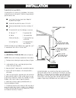
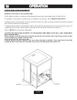
BIG E INSTALLATION
A. HORIZONTALLY THROUGH WALL
(refer to Figure 5)
NOTE:
Follow L-Vent chimney manufacturer’s instructions.
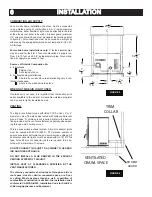
1. Positions stove, adhering to clearances shown in Figure
1.
2. Locate position of hole in wall; directly behind stove
exhaust vent (refer to
fi
gure 3).
3. Always maintain 3” clearance from combustible materials.
4. Install L-Vent wall thimble per L-Vent manufacturer’s
instructions.
5. Attach enough piping to penetrate and extend at least
6” beyond exterior walls. An 8-foot vertical pipe run is sug-
gested where possible to reduce the possibility of smoke
spillage in the event of a loss of negative pressure.
6. Attach cap and seal outside wall thimbles with non-
hardening waterproof mastic.
7. Terminations should not be located so that hot exhaust
gases can ignite trees, shrubs, or grass or be a hazard to
children. Exhaust gases can reach temperatures of 500
o
F
and cause serious burns if touched.
7
FIGURE 5
VERTICAL ROOF VENT
WALL
THIMBLE
6” MINIMUM CLEARANCE
TO ANY COMBUSTIBLE
SURFACE
CLEAN-OUT TEE
A 90 DEGREE ELBOW
MAY ALSO BE USED
L-VENT
ADAPTER
WALL STRAP
SEE VENT MANUFACTURER
FOR NUMBER AND SPACING
Содержание The Big E
Страница 25: ...ELECTRICAL DIAGRAM ELECTRICAL DIAGRAM 25 25 FIGURE 21 ...
Страница 27: ...27 27 ...