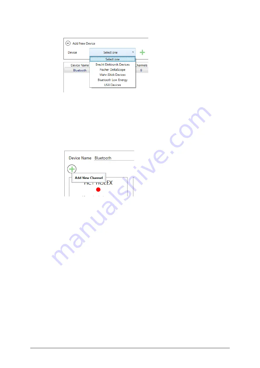
BRECHT ELEKTRONIK V-MUX Скачать руководство пользователя страница 13


P a g e  

13 | 24


5.


Under "ADD NEW DEVICE" click on "Select one". 


6.


Select the appropriate device from the list and click on it. 

7.


Add the selected device by clicking on "

+

" A new line with the device is displayed in the 

device view. 

8.


Depending on the added device, further settings must be made. To do this, click on the 
line in the table of the device view that shows the device to be set. 

9.


In the channel view below you will now see the settings to be made. For units that do not 

have pre-set channels, click on the "

+

" of the channel view: 


10.


Further down in the chapter "CONFIGURING MEASURING DEVICES" you will find detailed 
information on the settings of the individual devices. 

11.


The created virtual channels are displayed in the "Virtual MUX" view. 

12.


When you have added all the devices and made all the settings, click on "Connect" at the 
bottom right. The V-MUX software now establishes the connections to the measuring 
devices and the received measured values of the channels are output to the application 
software. 

Содержание V-MUX

Страница 1: ...measuring devices and transmit them uniformly to SPC QA ERP solutions The Brecht V MUX dongle is the licence carrier and provides 2 serial ports for communication between the V MUX software and the ap...

Страница 2: ...AL 5 Description 5 Communication with application software 5 Communication protocols 5 Download 5 Instrument connection 6 User Interface 7 V MUX CONFIGURATION 7 ADD a new device 9 FIRST START 11 CONFI...

Страница 3: ...f a Windows PC After use unplug the product again do not leave it unattended under voltage A built in visible LED lights up when voltage is applied The product may only be operated in dry rooms and mu...

Страница 4: ...ipment Act ElektroG to return electrical and electronic equipment to the manufacturer dealer or public collection point free of charge for disposal The symbol in these operating instructions indicates...

Страница 5: ...CATION WITH APPLICATION SOFTWARE The V MUX software supports several established communication protocols that can be selected with a mouse click Communication takes place classically via a COM port co...

Страница 6: ...l MUX Devices o Peter Hirt USB Probes DGHUSBCDC o TESA USB Probes MAHR INTEGRATED WIRELESS o All MAHR Devices with Integrated Wireless BLUETOOTH o Hoffmann Group HCT o Sylvac Bluetooth Measuring Devic...

Страница 7: ...V MUX software user interface The numbers in Fig 1 indicate the following ranges 1 V MUX configuration 2 menu to add new device 3 device view 4 channel view 5 overview of the virtual channels Virtual...

Страница 8: ...mmended to activate the extended transmission protocol e Extended transmission protocol In addition to the measured value the serial number that was previously added to the channel is also transmitted...

Страница 9: ...D A NEW DEVICE Image 3 Drop down menu for adding a new device Proceed as follows to add a new device Click on Select one Select the desired device from the list and click on it Add the selected device...

Страница 10: ...connected The large button at the bottom right is green when connected and indicates Disconnect A click on the button disconnects the connection 2 Channel View Image 5 Channels of a selected unit in t...

Страница 11: ...software The possible communication protocols can be found above in the chapter Communication protocols 2 Use the appropriate interface for the V MUX software RS232 or virtual keyboard We recommend u...

Страница 12: ...ta The transmission parameters must be set the same in the V MUX software and the application software BAUD Transmission speed the baud rate Usually 9600 baud DATABITS the number of data bits usually...

Страница 13: ...elow you will now see the settings to be made For units that do not have pre set channels click on the of the channel view 10 Further down in the chapter CONFIGURING MEASURING DEVICES you will find de...

Страница 14: ...of the serial interface for the USB probes is done in the pre configured channel configuration ADD CHANNEL Add device User Interface 1 Select device User Interface 2 Channel View User Interface 3 sele...

Страница 15: ...number Optionally assign the name of the measuring device and the serial number The coupling number the channel frequency as well as the eco mode can be changed but the change is only effective after...

Страница 16: ...ys of the measuring instruments If necessary switch on the radio modules according to the operating instructions ADD DEVICE If there is no Bluetooth device in the device view yet proceed as follows to...

Страница 17: ...nnel view Found measuring devices are displayed in the table Measuring devices in the area Bluetooth Low Energy CONFIGURATION in the channel view Place a check mark blue checkbox to each measuring dev...

Страница 18: ...ng devices and to the output interface and is then ready to perform measurements and transmit the measured values REMOVE CHANNEL Proceed as follows to remove a channel from the selected unit Right cli...

Страница 19: ...heckbox and click at the top right The configuration view of the Bluetooth devices changes back to the channel view REMOVE CHANNEL Proceed as follows to remove a channel from the selected unit Right c...

Страница 20: ...kbox and click at the top right The configuration view of the Bluetooth devices changes back to the channel view REMOVE CHANNEL Proceed as follows to remove a channel from the selected unit Right clic...

Страница 21: ...eckbox and click at the top right The configuration view of the Bluetooth devices changes back to the channel view REMOVE CHANNEL Proceed as follows to remove a channel from the selected unit Right cl...

Страница 22: ...ox and click at the top right The configuration view of the Bluetooth devices changes back to the channel view REMOVE CHANNEL Proceed as follows to remove a channel from the selected unit Right click...

Страница 23: ...ed in the directory AppData 1 open the Windows Explorer 2 Enter AppData in the address bar 3 change to subdirectory AppData Roaming Brecht Elektronik GmbH BrechtVMUX Logs 4 This folder contains the lo...

Страница 24: ...bH Rechbergstra e 6 73079 S en PHONE 49 7162 94 64 080 FAX 49 7162 94 64 081 MAIL info brecht elektronik de http www brecht elektronik de Legal Informationen Amtsgericht Ulm HRB 734565 Managing Direct...

Отзывы: