Assembly Instructions
36
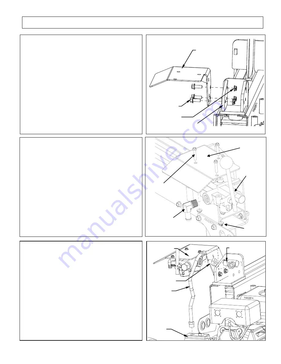
Step 7
Install the Valve Plate to the Beam
Assembly.
Use 3/8” x 1” Bolts and 3/8” Flange Nut.
Step 8
Install the Hose Barb Elbow to the Control
Valve port marked “Out”. Orient Hose Barb
Down as Shown.
Attach the Control Valve to the Valve Plate.
Use 1/4” x 1-3/4” Bolts and 1/4” Flange
Nuts
Valve plate
3/8” x 1” bolts
3/8” flange nuts
Beam assembly
Reducer fitting
High Pressure Elbow
Pump hose
Control valve
Pump
Step 9
Attach the Reducer Fitting and the High
Pressure Elbow to the Control Valve port
marked “IN”. Orient the High Pressure
Elbow as shown.
Attach Pump Hose to the Pump, use Pipe
Sealant on threads into Pump.
Attach the loose end to the High Pressure
Elbow, Pipe Sealant is not needed.
¼” x 1-3/4” Bolts
Valve Plate
Control Valve
Hose barb elbow
¼” Nuts
Содержание MPCLS2013E.2
Страница 2: ...Hazard Signal Word Definitions 2 ...
Страница 25: ...Parts Breakdown Exploded View Rev E 2 25 ...
Страница 33: ...Assembly Instructions 33 ...


