USER MANUAL
19
1.
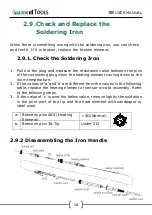
Pull out the iron tip by the needle at the soldering handle holder. the
iron tip and the iron tip encloser
①
are in together.
2.
Pull out the heating element
③
towards the iron tip of the iron
handle
⑧
.
3.
Push the handle cord
(
12
)
lightly forwards and pull the sensor
④
,
PCB for line connection
⑥
and handle cord out of the iron handle
⑧
(towards the tip of the handle).
NOTE:
Do not use metal tools such as pliers to remove tip or Tip
encloser from the iron handle.
2.9.3 Measure the Resistance before
Replacing
NOTE:
Measure the resistance when the heating element is at
room temperature.
1.
Resistance value of heating element is
<
4Ω.
2.
Resistance value of sensor is
<
10Ω.
3.
If the resistance value is not normal, replace the heating element or
sensor element. Refer to the instructions included with the
replacement part.
2.9.4 Measure the Resistance after
Replacing
After replacing the heating element:
1.
Measure the resistance value between pins 4 & 2 or 1, pins 5 & 2 or
1. If it is not ∞, the heating element and sensor are touching. This
will damage the PCB.
2.
Measure the resistance value “a”, “b” and “c” to confirm that the leads
are not twisted and that the grounding wire is properly connected.

