background image

Heavy Haul Trailers

34

WARNING!  

Attempting to couple the trailer at an improper height could result in a false or 

improper coupling and could cause damage to the fifth wheel or trailer.

4.

Back under the trailer, keeping the trailer kingpin centered in the crotch of the fifth wheel.

5.

After picking up the trailer with the fifth wheel, STOP, then continue backing until the fifth wheel

locks firmly on the king pin.

6.

Back up tight to the kingpin. Pull forward to test the completeness of the coupling as an initial

check.

WARNING!  

If you do not obtain a proper coupling, repeat steps 3 through 6.  Do not use a fifth 

wheel which fails to operate properly.

7.

Visually check to see that the kingpin is in the fifth wheel locks, ensure that it is not overhanging

the fifth wheel or caught in a grease groove. There should be no gap between the trailer plate
and the fifth wheel.

WARNING!  

A direct visual inspection is required to assure a proper coupling.  Several types of 

improper couplings will pass the initial pull test and the sound is unreliable.  Do not take for 
granted that the trailer is properly coupled.

8.

Connect the light cord and the brake lines and be sure any slack in the lines is supported and the

brake lines do not become tangled.

9.

If your fifth wheel is equipped with a manual secondary lock, check to see that it is properly

engaged.

10.

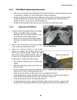
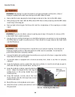
Using the hydraulic controls, extend the main deck cylinders to raise the deck high enough to

allow the shim legs to be rotated down.  See Fig. 3-10.

11.

Using the hydraulic controls, rotate the shim legs

down.  Adjust the length of the shim legs by
pulling down on the spring loaded base and
inserting shims.

12.

Using the hydraulic controls, retract the main

deck cylinders until the shim legs make contact
with the trailer deck.

13.

Shut off the gas on the hydraulic unit engine.

14.

Attach the trailer air lines and electrical cord to

the gooseneck.

Shim Leg
rotated DOWN

FIG. 3-10.

Positioning the Shim Arms

Содержание H550 Series

Страница 1: ...Owner s Manual H550 H650 M400 Series Heavy Haul RGN Trailers Publication No 9001448 Rev 1 Toll Free 1 877 533 3133 www brandt ca ...

Страница 2: ......

Страница 3: ...ilers WARNING This Owner s Manual contains safety information and instructions for your trailer You must read this manual before loading or towing your trailer You must follow all safety precautions and instructions ...

Страница 4: ...Heavy Haul Trailers ...

Страница 5: ...3 2 Driving Too Fast for the Conditions 11 2 3 3 Trailer Not Properly Coupled to the Tractor 12 2 3 4 Matching Trailer and Tractor 12 2 3 5 Worn Tires Loose Wheels and Lug Nuts 13 2 3 6 Improper Loading 15 2 3 7 Unsafe Load Distribution 16 2 3 8 Shifting Cargo 16 2 3 9 Inappropriate Cargo 17 2 3 10 Inoperable Lights 17 2 3 11 Hazards from Modifying Your Trailer 18 2 4 Reporting Safety Defects 18 2...

Страница 6: ...l Operating Instructions 39 3 5 1 1 Coupling the Fifth Wheel 39 3 5 1 2 Uncoupling the Fifth Wheel 40 3 5 2 Disconnecting the Gooseneck from the Deck 41 3 5 3 Connecting the Gooseneck to the Deck 42 3 5 4 Extension Load Shim Instructions 43 3 6 Trailer Deck Shims 44 3 7 Trailer Suspension and Brake Controls 45 3 8 Loading and Unloading Procedures 47 3 9 Operating Precautions 48 3 9 1 Loading and U...

Страница 7: ... 9 3 3 Steps for Maintaining Proper Tire Pressure 53 4 9 4 Tire Size 54 4 9 5 Tire Tread 54 4 9 6 Tire Balance and Wheel Alignment 54 4 9 7 Tire Repair 54 4 9 8 Tire Fundamentals 55 4 9 9 Matching Dual Tires 56 4 9 9 1 Tire Measurement 56 4 10 Wheel Hub Installation 57 4 10 1 Single Hub Nut System 57 4 10 2 Double Hub Nut System 57 4 11 Service Record 58 CHAPTER 5 Troubleshooting 59 CHAPTER 6 Addi...

Страница 8: ...s not read this manual is not qualified to operate this machine Read this manual before proceeding with any inspections or repairs on this machine Use the Table of Contents as a guide Keep all manuals for future use Contact Brandt if you need additional copies of this manual 1 1 Operator Orientation The directions left right front and rear as mentioned throughout the manual are as seen from the to...

Страница 9: ...s equipment until such information has been reviewed Annually review this information Make these periodic reviews of Safety and Operation a standard practice for all of your equipment An untrained operator is unqualified to operate this machine A sign off sheet is provided for your record keeping to show that all personnel who will be working with the equipment have read and understood the informa...

Страница 10: ...igger Kit 141 3 58m 123 3 12m Tare Trailer 26 deck 30 200 lbs 13 700 kg 28 600 lbs 12 986 kg Tare Extension 3 000 lbs 1360 kg Deck Lengths 24 26 6 Extension 24 26 88 112 154 5 16 172 5 16 25 11 8 65 9 5 16 6 3 178 1 16 60 60 H650 65 Ton Square Tail Trailer c w Deck Gooseneck Extensions 50 24 1 16 27 1 2 88 112 50 8 24 59 7 1 4 25 11 178 9 16 60 60 27 1 2 154 5 16 172 5 16 H650 65 Ton Square Tail T...

Страница 11: ... 63 500 kg Payload 110 200 lbs 50 000 kg Deck Width 120 3 05m Deck Width c w Outrigger Kit 141 3 58m Tare 27 800 lbs 12 600kg 88 112 150 168 25 8 8 59 3 1 2 14 6 1 2 60 60 H550 55 Ton Blunt Tail Trailer c w Gooseneck Extension 50 24 32 when used with Jeep and Booster ...

Страница 12: ...re 29 000 lbs 13 150kg 89 113 155 173 25 11 10 62 11 18 1 1 4 60 60 65 Ton Beaver Tail Trailer c w Flip Front Section 50 27 5 16 66 3 4 89 113 155 173 25 11 10 62 11 18 1 1 4 60 60 H650 65 Ton Beaver Tail Trailer c w Gooseneck Extension 50 27 5 16 66 3 4 89 113 155 173 25 11 10 62 11 18 1 1 4 60 60 65 Ton Beaver Tail Trailer c w Flip Front Section 50 27 5 16 66 3 4 88 112 150 168 23 6 8 59 3 17 2 ...

Страница 13: ...m Deck Width c w Pull Out Outriggers 13 3 96m Deck Width c w Swing Out Outriggers 10 6 3 20m Tare No Gooseneck Extension 19 300 lbs 8 750kg 89 113 155 173 25 11 10 62 11 18 1 1 4 60 60 65 Ton Beaver Tail Trailer c w Flip Front Section 50 27 5 16 66 3 4 82 120 29 6 5 56 3 13 7 54 54 M400 40 Ton Trailer 54 Axle Spacing c w Gooseneck Extension 48 17 26 to 60 52 11 89 113 155 173 25 11 10 62 11 18 1 1...

Страница 14: ... 4 Description and Location of Major Components RGN Trailers E D C B A A Goose Neck B Base Trailer Deck C Rear Axle Section D Optional Front Flip Section E Optional Trailer Deck Extension FIG 1 2 Major Components RGN Trailers ...

Страница 15: ...Heavy Haul Trailers 8 ...

Страница 16: ...e equipment or in the area so that they too may take any necessary safety precautions that may be required You are responsible for the safe operation and maintenance of this equipment Make sure that all persons who operate maintain or work near this equipment know the contents of this manual You are the key to safety These safety precautions protect you and the people near you Include these precau...

Страница 17: ...NING or CAUTION is used with the Safety Alert Symbol DANGER Is reserved for a hazard that if not avoided will result in death or serious injury WARNING Indicates a hazard that if not avoided could result in death or serious injury Caution Shows a hazard that if not avoided could result in injury Notice Indicates that your heightened awareness is required to avoid practices not related to personal ...

Страница 18: ...messages mean Note Some of these messages will not be used on this product They are shown for example only Notice Replace safety signs when they become damaged Make sure to include safety signs on replacement parts New safety signs are available from Brandt Crush Hazard Pinch Hazard High Voltage Stop Cutting Hazard Entanglement Hearing Protection Hard Hat Heavy Object Lock out Location Eye Protect...

Страница 19: ...iler capacity Do not operate the trailer at speeds that exceed the designed ratings Use tools applicable to the work Use power tools to loosen threaded fasteners only Do not use SAE tools on SI metric fasteners Use the correct lifting equipment for moving heavy parts Follow recommended procedures for removal and installation of parts Keep the area clear of bystanders especially children Have a fir...

Страница 20: ...e maintenance problems For these reasons the maximum towing capacity of your tractor should not be exceeded The towing capacity of your tractor in terms of maximum Gross Trailer Weight GTW and maximum Gross Combined Weight Rating GCWR can be found in the tractor s Owner s Manual DANGER Use of a tractor with a towing capacity less than the Gross Vehicle Weight Rating of the trailer can result in lo...

Страница 21: ... the tractor Be sure the hitch components are tight before coupling the trailer to the tractor WARNING An improperly coupled trailer can result in death or serious injury Do not move the trailer until The trailer s kingpin is locked to the tractor s fifth wheel The trailer jack s are fully retracted Do not tow the trailer on the road until Tires and wheels are checked The trailer brakes are checke...

Страница 22: ... at 60 kph 1mile at 40 mph before checking tire pressure WARNING Inflate tires to the pressure stated on the Certification VIN label Improper tire pressure may cause an unstable trailer Blowout and loss of control may occur Death or serious injury can result Make sure of proper tire pressure before towing trailer The tightness of the wheel nuts or bolts is very important in keeping the wheels prop...

Страница 23: ...bolts are prone to loosen after being first assembled Death or serious injury can result Check wheel nuts or bolts for tightness on a new trailer and after re mounting a wheel at 100 km 60 miles WARNING Inadequate wheel nut or bolt torque can cause a wheel to separate from the trailer leading to death or serious injury Verify wheel nuts or bolts are tight before each tow ...

Страница 24: ...an be used to determine approximate axle weight The Air Control Box has a chart to convert the air pressure reading to axle weight If your trailer is equipped with a Tire Loading Information Placard mounted next to the Complaisance label the cargo capacity weight stated on that placard is only a close estimate The GVWR and GAWR are listed on the Complaisance label normally located on the front lef...

Страница 25: ...vity as low as possible Improper tongue weight load distribution can result in loss of control of the trailer leading to death or serious injury WARNING Make certain that axle weights are within the allowable range Be sure to Distribute the load evenly right and left Keep the center of gravity low Distribute the load front to rear to provide proper suspension weight 2 3 8 Shifting Cargo Since the ...

Страница 26: ...ing towed Fuel stored in the tank of an on board hydraulic power pack 2 3 10 Inoperable Lights Be sure that all of the lights on your trailer are functioning properly before towing your trailer Lights on a trailer are controlled via a connection to the tractor generally a multi pin electrical connector Check the trailer tail and clearance lights by turning on your tractor headlights Check the trai...

Страница 27: ...Brandt as well as notifying the appropriate governing agency listed below The governing agencies may open an investigation upon receiving similar complaints and if it finds a safety defect exists in a group of vehicles However it cannot become involved in individual problems between you and your dealer or manufacturer 2 4 1 Brandt Contact your local Brandt dealer directly or Brandt Customer servic...

Страница 28: ... to prevent damaging the cargo or the trailer Place concentrated heavy loads over structural beams when loading Tie down securely before moving or transporting Check tie downs frequently when transporting and keep them tight Do not exceed the load concentration and total load carrying specifications of the trailer Install lights or flags on the load if it extends beyond the deck Do not side load 2...

Страница 29: ...ollowing illustrations show the position and content of the various safety decals on the trailer If safety decals ever become damaged removed or illegible new decals must be applied New decals are available from your authorized dealer Both Sides Both Sides ...

Страница 30: ...21 Heavy Haul Trailers ...

Страница 31: ...Heavy Haul Trailers 22 Both Sides ...

Страница 32: ...23 Heavy Haul Trailers Both Sides ...

Страница 33: ...e passing distance without a trailer Use lower gears for climbing and descending grades Do not ride the brakes while descending grades they may get so hot that they stop working Then you will potentially have a runaway tractor and trailer To conserve fuel don t use full throttle to climb a hill Instead build speed on the approach Slow down for bumps in the road Take your foot off the brake when cr...

Страница 34: ...in provides four unique pin positions A Trailer Deck Extension that extends the deck by 6 feet Deck Outriggers that are used to support extremely wide equipment Back End Ramp Kit that acts as a stop on the trailer deck and assists certain loads up over the tire and onto a bolster Light and Flag Kit to alert other drivers when hauling extremely wide equipment Fender Kits for the Gooseneck and the R...

Страница 35: ...ment Look for irregular tire wear Refer to maintenance section for procedure 3 2 3 10 000 mile 16 000 km Inspection 1 Check the function and adjustment of the brakes on each axle The pads should not drag on the drum rotor when the brakes are released 2 Check the tire inflation pressures and tread wear Always match tires with tread wear that is worn to 1 8 in difference If unusual or excessive tire...

Страница 36: ...fety catch engaged to prevent accidental disconnection Ensure that air and electrical lines are properly secure against tangling snagging and chafing with sufficient slack for turns 2 Lights and Reflectors Check front trailer clearance and identification lights are clean and operating Ensure reflectors are present and clean Area 2 Fifth Wheel Coupling Area 1 Fifth Wheel Lower Secure mount to frame...

Страница 37: ... are clean and operating Reflectors clean 3 Frame and Body Frame and cross members not bent cracked damaged or missing Body parts not damaged or missing 4 Placarding Proper identification of trailer load 5 Cargo Securement Cargo properly loaded side to side and back to front Check cargo tie downs and ensure they are tight National Safety Code Standard 10 Cargo Securement Ensure concentrated load i...

Страница 38: ... or chafing 2 Suspension Condition of air bags beam bushings fasteners and U bolts Axle alignment Look for unusual tire wear Condition of shock absorbers Look for leaking Area 7 Rear of Trailer 1 Lights and Reflectors Rear clearance and identification lights clean and operating Reflectors are clean Taillights clean and operating 2 Cargo Securement Cargo properly loaded side to side and back to fro...

Страница 39: ...roper connection of air brake glad hands and secure contact of electrical connection 4 Start tractor engine 5 Build up air pressure in the tractor trailer systems 6 Turn on lights and inspect for proper function of Clearance lights Identification lights Turn signals and 4 way flashers Side marker lights Tail lights Stop lights 7 Check the function of brakes Apply service brakes Apply parking brake...

Страница 40: ...operly trained persons should attempt to operate the controls Never place any body part beneath the load or any part of the frames when the hydraulic cylinders are in motion or when the hydraulics are supporting the trailer or the load with no mechanical stops in place Stand well clear of any hydraulically actuated components while they are in motion One person operation is recommended for safety ...

Страница 41: ...ailers 32 3 4 2 Gooseneck Hydraulic Controls Pressure Gauge Hydraulic Control Valve Hydraulic Power Pack Access Ports Tractor Hydraulic System Hydraulic Power Pack Selector Valve FIG 3 7 Gooseneck Hydraulic Controls ...

Страница 42: ... kingpin in the cradle of the fifth wheel STOP 3 Check to see that the trailer is at the proper height for coupling The leading edge of the trailer plate should initially contact the fifth wheel top bearing surface behind its pivot axis as the tractor or trailer backs under the trailer If adjustment is required do the following Ensure the gooseneck lock pin is in place and locked Dump the suspensi...

Страница 43: ...NING A direct visual inspection is required to assure a proper coupling Several types of improper couplings will pass the initial pull test and the sound is unreliable Do not take for granted that the trailer is properly coupled 8 Connect the light cord and the brake lines and be sure any slack in the lines is supported and the brake lines do not become tangled 9 If your fifth wheel is equipped wi...

Страница 44: ...engine on the gooseneck s hydraulic power unit or connect and engage the tractor s hydraulic system Make sure the selector valve is positioned correctly 8 Using the hydraulic controls extend the main deck cylinders to rotate the gooseneck to a position that will allow the shim legs to be rotated up See Fig 3 11 9 Using the hydraulic controls rotate the shim legs UP 10 Using the hydraulic controls ...

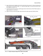
Страница 45: ... 1 Disengage the gooseneck lock pin See Fig 3 14 Fig 3 12 shows the lock pin in the engaged position 2 Dump the suspension air from the tractor jeep trailer and booster 3 Disconnect the air lines and electrical plug between the tractor jeep and the trailer 4 Start the engine on the hydraulic power unit or engage the tractor s hydraulic system Make sure the selector valve is positioned correctly 5 ...

Страница 46: ...connection base lifts off the deck pins by approximately 1 4 See Fig 3 17 8 Return to the tractor and slowly drive ahead disconnecting the gooseneck from the trailer FIG 3 16 Lowering the Trailer Deck 1 1 2 Lock Pin retracted FIG 3 15 Rotating the Shim Arms Shim Arm rotated UP FIG 3 14 Gooseneck Lock Pin Lock Pin Rotate and Pull to disengage Pin Drive Lug Trough Pin Gooseneck Support Arm Connectio...

Страница 47: ...ck pins drive forward and repeat steps 4 5 6 Using the hydraulic controls retract the gooseneck support arm until the gooseneck connection base is resting on the trailer deck Make sure the drive lug is behind the trough pin See Fig 3 18 7 Using the hydraulic controls extend the main deck cylinders to raise the deck high enough to allow the shim legs to be rotated down See Fig 3 18 8 Push on the go...

Страница 48: ...ailer is in good condition and tight 2 Back up close to the trailer centering the kingpin in the cradle of the fifth wheel STOP 3 Check to see that the trailer is at the proper height for coupling The rollers of the trailer should initially contact and roll up the tractor or jeep ramps WARNING Attempting to couple the trailer with improper ramps could result in a false or improper coupling and cou...

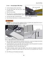
Страница 49: ...rical cord to the gooseneck 3 5 1 2 Uncoupling the Fifth Wheel 1 Set the emergency brake on the tractor 2 Set the trailer brakes with the tractor trailer protection switch 3 Block the trailer wheels 4 The suspension air should be dumped from the air bags after the trailer parking brake is applied 5 Disconnect the light cord and brake lines 6 Ensure the anti dive pin is in place and locked If not t...

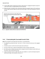
Страница 50: ...eel and pull the tractor forwards 4 Remove link retainers rotate links to storage hooks See Fig 3 19 5 Back tractor under the gooseneck and recouple the fifth wheel 6 Disengage anti dive pin See Fig 3 22 7 Place temporary blocking between gooseneck and tractor or jeep frame See Fig 3 20 8 Return to the tractor air up the suspension and pull forward FIG 3 19 Link Storage rotation FIG 3 20 Blocking ...

Страница 51: ...engagement See Fig 3 24 6 Inspect to ensure drive lugs will engage See Fig 3 23 7 Decouple the fifth wheel and pull the tractor forward 8 Rotate the links to desired setting and install link retainers 9 Back tractor under the gooseneck and recouple the fifth wheel 10 Connect air and electrical lines between tractor or jeep and the trailer Note If the gooseneck drive lugs do not properly engage the...

Страница 52: ...43 Heavy Haul Trailers 3 5 4 Extension Load Shim Instructions ...

Страница 53: ...e and referring to the load chart To adjust the shims 1 Place blocks under the trailer main rails near the end 2 Loosen the Retaining Bolt on both sides 3 Dump the air pressure in the trailer axle suspension A gap between the deck frame and the Rear Axle Section will develop 4 Insert the required shims and retighten the retaining bolt Always shim both sides of the trailer equally 5 Pressurize the ...

Страница 54: ...lief Valve used when dumping the air from the air bags the Emergency Brake Release Valve the switch for the Rear Strobe Lights and the switch for the optional Strobe Light Battery Back up A chart on the inside of the door outlines the air bag pressure required for different weight loads FIG 3 28 Control Box Components SUSPENSION LOAD CHART Suspension Air Gauge Strobe Light Switch Strobe Light Batt...

Страница 55: ...e to the dead bands of the Height Control Valve Engage the selected Height Control Valve setting by dumping and re inflating the suspension AIR SUSPENSION PRESSURE LOAD SCALE REQ D PRESSURE PSI LOAD PER AXLE LBS LOAD PER AXLE KG 80 25 000 11 340 74 23 000 10 433 66 21 000 9 525 60 19 000 8 618 53 17 000 7 711 46 15 000 6 804 39 13 000 5 897 32 11 000 4 990 26 9 000 4 082 19 7 000 3 175 12 5 000 2 ...

Страница 56: ...ING The centerline of the tracks or tires of the machine being transported MUST be positioned on the trailer main deck not on the extensions The extensions are NOT designed to carry the full weight of the machine 5 Use extreme caution when loading the machine on the trailer GO SLOWLY The load must be centered on the trailer DO NOT overload one side Position the machine for equal weight distributio...

Страница 57: ... limits depending on their construction and the time of year Overloading can cause road damage inadequate braking capacity tire suspension and or frame damage or failure and lose of vehicle control 3 9 4 Speed Do not exceed maximum highway speed limits loaded or unloaded With long or high center of gravity loads vehicle stability is reduced SLOW DOWN 3 9 5 Load Securement Improperly secure loads c...

Страница 58: ...d the gooseneck cylinders may be raised or lowered to change the overall height Any such adjustments are only for short distances such as clearing over railroad tracks or under overpasses The gooseneck MUST be returned to Shim Leg fixed support be for continuing or damage to the trailer could occur WARNING Using the hydraulics to alter the load height may affect the suspension travel and trailer h...

Страница 59: ...Heavy Haul Trailers 50 ...

Страница 60: ...ithium based grease 2 Gooseneck Hydraulic System Use 60 liters of Valpar HVI 22 Hydraulic Oil Brandt part no 603281 when empty 3 Hydraulic System Engine Oil 10W30 summer 5W30 winter 4 Wheel Hubs Use SAE 75 90 Synthetic Gear Oil 5 Storing Lubricants Your machine can operate at top efficiency only if clean lubricants are used Use clean containers to handle all lubricants Store them in an area protec...

Страница 61: ...ir reservoir for leaks Drain any condensation buildup 8 Check the brake drums rotors for wear and signs of over heating 9 Check the air suspension system for leaks and damage 10 Check the complete electrical system for proper operation 11 Check all reflectors and marking devises 12 Check the fuel level in the hydraulic power unit engine 13 Check the oil level in the hydraulic power unit engine 14 ...

Страница 62: ...ck the hydraulic power unit engine s air cleaner Clean if necessary 4 3 4 Semi Annually 1 Grease the slack adjusters drum brakes 2 places See Fig 4 4 4 3 5 Annually 1 Change oil in the hubs 2 Clean and inspect the brake chambers 3 Change the oil and filter in the hydraulic power unit oil reservoir 4 3 6 Hydraulic Power Unit Engine Refer the engine s operator and service manual 4 3 6 1 After first ...

Страница 63: ...lts 500 25 680 30 Spider Anchor Bolt 12 1 4 1 2 20 UNF Gr 8 100 136 Spider Anchor Bolt 16 1 2 1 2 20 UNF Gr 5 75 101 Bolt On Spider 1 2 20 UNF Gr 5 75 101 Cam Brackets 1 4 20 UNC Gr 5 8 11 Air Chamber Type 9 16 7 16 14 UNC 30 40 40 54 Air Chamber Type 20 30 5 8 11 UNC 100 115 136 156 COMPONENT DESCRIPTION IN LBS NM Hub Cap 180 10 21 3 Disc Brake Dust Shield Clamp 1 2 wide band 60 10 7 1 Disc Brake...

Страница 64: ...ULL level Use SAE 75 90 Synthetic Gear Oil 10 bolt hub require approximately 600ml of oil when empty Use the FULL line as a guide 4 7 Wheel Nut Torque Requirements Caution Improperly torqued wheel nuts can cause a loss of implement control and machine damage Torque wheel nuts to 475 25 ft lbs Check torque as outlined in Section 3 2 Check all wheel nuts for tightness before the first trip Failure t...

Страница 65: ...uter wheels or outer tires and rims 4 Attach a steel measuring tape to a hook and the hook over the kingpin Measure the distance A and B from the king pin to the ends of the forward axle The difference between the A and B measurements must not exceed 1 8 3 2mm See Fig 4 8 5 Measure the distance C and D between the front and middle axle centers The difference between C and D measurements must not e...

Страница 66: ...are the most important things you can do to avoid tire failure such as tread separation or blowout and flat tires These actions along with other care and maintenance activities can also Improve vehicle handling Help protect you and others from avoidable breakdowns and accidents Improve fuel economy Increase the life of your tires This booklet presents a comprehensive overview of tire safety includ...

Страница 67: ...ds and certification labels are permanently attached to the trailer near the left front 4 9 3 Tire Inflation Tire inflation pressure is the level of air in the tire that provides it with load carrying capacity and affects the overall performance of the vehicle The tire inflation pressure is a number that indicates the amount of air pressure measured in kilo pascals kPa or pounds per square inch ps...

Страница 68: ... pressure is too high in any of the tires slowly release air by gently pressing on the tire valve core with the edge of your tire gauge until you get to the correct pressure 4 If the tire pressure is too low note the difference between the measured tire pressure and the correct tire pressure These missing pounds of pressure are what you will need to add Note It is acceptable to top up nitrogen fil...

Страница 69: ...in the bottom of the tread grooves When they appear even with the outside of the tread it is time to replace your tires 4 9 6 Tire Balance and Wheel Alignment To avoid vibration or shaking of the vehicle when a tire rotates the tire must be properly balanced This balance is achieved by positioning weights on the wheel to counterbalance heavy spots on the wheel and tire assembly A wheel alignment a...

Страница 70: ...damental characteristics of the tire and also provides a tire identification number for safety standard certification and in case of a recall Rim Diameter Radial Ratio of height to width aspect ratio Nominal width of tire in millimeters Max Load Max Pressure Max Speed Tire Architecture DOT Markings Brand Tire here User Information Load and Speed Index FIG 4 10 Basic Information on Heavy Truck Tire...

Страница 71: ... circumference are allowed Note The smaller of the two tires should be mounted in the inside position 4 9 9 1 Tire Measurement Measure the circumference of the tire with a tape measure after the tire is mounted on a rim and inflated but NOT mounted on the trailer See Fig 4 11 A straight edge square or string gauge can be used to check the tires mounted on the trailer See Fig 4 12 Note The dimensio...

Страница 72: ...Verify that the wheel rotates freely when adjustment is complete 4 10 2 Double Hub Nut System 1 Install and tighten the inner nut to 200 ft lbs 271 N m 2 Spin the wheel at least one full revolution 3 Loosen the nut one full turn 4 Tighten the inner nut to 50 ft lbs 68 N m 5 Loosen the nut 1 4 turn 90 degrees 6 Install the locking washer 7 Install the outer jam nut and tighten to 300 400 ft lbs 407...

Страница 73: ...tion C Brake Drums Rotors C Air Suspension for leaks and damage C Electrical System C Reflectors and marking devises C Hydraulic Power Pack C Oil level in Reservoir C Goose Neck Lock Pin Weekly L Goose Neck Support Arm Pivot L Goose Neck Base Pivot L Hydraulic Cylinder Mounting Pins L Cam Shaft Bushings Drum Brakes C Wheel Nut Torque Monthly C Brake Pad lining thickness C Kingpin for wear and dama...

Страница 74: ... Replace air spring Leaking or broken line in air suspension system Inspect and test for leaks or pinched air lines Repair as required Malfunctioningheightcontrol valve Inspect test or replace if necessary One Air Spring is flat Air Spring is leaking or punctured Replace air spring Supply lines pinched or broken Repair or replace if necessary Air suspension deflates rapidly when parked Leak in the...

Страница 75: ...place if necessary Brake pads worn or glazed over Replace brake pads Slow brake application or release Excessive travel in brake chamber push rod Adjust brakes Restriction in hose or line Repair or replace hose or line Defective brake valve s Replace defective valve s Brakes grabbing Oil grease or foreign material on brake pads Replace brake pads Brakes out of adjustment Adjust brakes Brake drum r...

Страница 76: ...traighten align or replace axle Tires not properly matched Match tires Improperly acting brakes Correct brakes as required Rapid stopping Apply brakes slowly when approaching stops Excessive speed in turns Reduce speed Scuffed tires Over or under inflation Inflate to recommended pressure Excessive speed in turns Reduce speed Tracking to one side Leaking or flat air spring Replace air spring Bent a...

Страница 77: ...ate Insufficient oil level Fill reservoir to proper level Restriction of oil flow Remove restriction Pump is worn Repair or replace pump Broken key or keyway in drive Repair or replace key Hydraulic hose not connected Connect the hose Worn control valve Repair or replace valve Cylinder will not hold pressure Air in the hydraulic system Bleed system by making several cycles Internal leak in cylinde...

Страница 78: ... otherwise noted throughout this manual Check the tightness of the bolts periodically using the bolt torque chart as a guide Replace hardware with the same strength bolt Torque figures are valid for non greased or non oiled threads and heads unless otherwise specified Do not grease or oil bolts or cap screws unless specified in this manual When using locking elements increase the torque values by ...

Страница 79: ...0 700 1700 1250 2140 1580 2700 2000 3400 2500 1 1 2 990 730 1250 930 990 730 1250 930 2250 1650 2850 2100 3600 2650 4550 3350 Torque values listed are for general use only based on the strength of the bolt or screw DO NOT use these values if a different torque value or tightening procedure is given for a specific application For plastic insert or crimped steel type lock nuts for stainless steel fa...

Страница 80: ...2700 2000 M33 900 665 1150 850 1750 1300 2200 1625 2500 1850 3150 2325 2900 2150 3700 2730 M36 1150 850 1450 1075 2250 1650 2850 2100 3200 2350 4050 3000 3750 2770 4750 3500 Torque values listed are for general use only based on the strength of the bolt or screw DO NOT use these values if a different torque value or tightening procedure is given for a specific application For stainless steel faste...

Страница 81: ... 6 4 Tapered Pipe Thread Torque Suggested Wrenching Torque for Tapered Pipe Thread Fittings Tapered Pipe Thread with Sealant Tapered Pipe Thread without Sealant Thread Size N m lb ft Thread Size N m lb ft 1 16 27 UNF 15 10 1 16 27 UNF 20 15 1 8 27 UNF 20 15 1 8 27 UNF 25 20 1 4 18 UNF 25 20 1 4 18 UNF 35 25 3 8 18 UNF 35 25 3 8 18 UNF 45 35 1 2 14 UNF 45 35 12 14 UNF 60 45 3 4 14 UNF 60 45 3 4 14 ...

Страница 82: ...5 1 4 30 3 8 2 6 1 2 45 1 2 3 11 1 2 45 5 8 3 12 90 TABLE 6 6 SAE to Metric Conversion SAE Unit Conversion Factor SI Units Metric ft min x 0 3048 Metres min m min ft s x 0 3048 Metres s m s US gallon x 3 7854 Litres L US gal min GPM x 3 7854 Litres min L min hp x 0 7457 Kilowatts kW in x 2 54 Centimetres cm in x 25 4 Millimetres mm in3 x 16 3871 Cubic centimetres cm3 or cc lb x 0 4535 Kilogram kg ...

Страница 83: ...per minute ft s Feet per second GPM U S gallons per minute hp Horsepower HPU Hydraulic power unit Hz Hertz in3 Cubic inches ID Inside diameter lb Pound lbf Pounds force lbf ft or ft lb Pound feet or foot pounds lbf in or in lb Pound inches or inch pounds mph Miles per hour N A Not applicable OD Outside diameter OEM Original Equipment Manufacturer oz Ounce PH Phase psi Pounds per square inch RPM Re...

Страница 84: ...69 Heavy Haul Trailers Date Maintenance Performed Maintenance Records ...

Страница 85: ...Heavy Haul Trailers 70 Date Maintenance Performed Maintenance Records ...

Страница 86: ...71 Heavy Haul Trailers Date Maintenance Performed Maintenance Records ...

Страница 87: ...Heavy Haul Trailers 72 Date Maintenance Performed Maintenance Records ...

Страница 88: ......

Страница 89: ...Toll Free 1 888 227 2638 www brandt ca ...

Отзывы: