EN
2 /
INSTALLING YOUR APPLIANCE
ASSEMBLING THE HOOD
Warning
The hood must be installed in compli-
ance with all applicable regulations concern-
ing the ventilation of premises. In France
these regulations are described in DTU 61.1
from the CSTB. In particular, the evacuated air
should never be conveyed to a duct used to
evacuate smoke from appliances that use gas
or other combustible fuels. Unused ducts may
only be used after approval from a competent
specialist.
The minimum distance between the cooking
surface and the lowest part of the hood must
be 70 cm at least. If the instructions for the hob
installed under the hood specify a distance of
more than 70 cm, this requirement must be
respected.
F
•
•
Pic 3
Pic 4
Pic 5
Pic 6
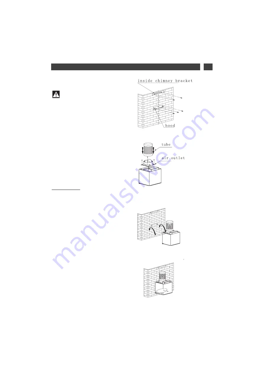
Fixing to the wall:
-Draw a vertical line on the wall centered on
the cook top.
-In a suitable position, drill 3 holes and Insert
the 3 wall plugs for the hook. Drill 2 holes and
insert the 2 wall plugs for the inside chimney
bracket (Pic 3)
-Screw the hook to the wall with 3 screws.
Screw the inside chimney bracket to the wall
with 2 screws. Ensure they are perfectly
leveled. (Pic 3)
-Use 4 screws to fix the air outlet onto the
motor unit and insert the extension tube. (Pic
4)
- Hang the motor unit in the hook (Pic 5) and
fix the motor unit with 2 safety screws (Pic 6)
57
Содержание BHB6602X
Страница 3: ......
Страница 10: ...FR 1 A L ATTENTION DE L UTILISATEUR DESCRIPTION DE VOTRE APPAREIL 9 ...
Страница 15: ......
Страница 25: ......
Страница 33: ... DESCRIPCIÓN DEL APARATO 500 980 500 600 900 7 8 R20 500 312 272 R30 225 60 150 32 ...
Страница 38: ......
Страница 40: ......
Страница 55: ...EN 1 NOTICES TO THE USER DESCRIPTION OF YOUR APPLIANCE 54 ...
Страница 60: ......
Страница 61: ... Pic 3 Pic 3 Pic 11 Pic 15 Pic 12 Pic 15 into the upper duct Pic 16 Pic 14 Pic 15 Pic 16 60 ...
Страница 63: ...62 ...
Страница 64: ...63 ...
Страница 65: ...64 ...
Страница 70: ...69 70 75 76 77 77 78 79 81 82 83 84 84 85 85 86 87 88 ...
Страница 77: ...1 PRO UŽIVATELE CZ POPIS PŘÍSTROJE 76 500 980 500 600 900 7 8 R20 500 312 272 R30 225 60 150 ...
Страница 82: ......
Страница 83: ...Obr 15 Obr 16 82 ...
Страница 84: ...83 zastavit Nízká Střední Vysoká Světlo ...
Страница 85: ...84 ...
Страница 86: ...85 ...
Страница 89: ...88 ...
Страница 92: ......
Страница 99: ...1 MÆRKNINGER TIL BRUGER DK BESKRIVELSE AF APPARATET 500 980 500 600 900 7 8 R20 500 312 272 R30 225 60 150 98 ...
Страница 102: ...101 ...
Страница 104: ......
Страница 105: ...104 Figur 15 Figur 16 Figur 3 Figur 3 Figur 11 Figur 15 Figur 12 Figur 15 Figur 16 Figur 14 ...
Страница 106: ...105 ...


